Director Load Balancing – NetScaler 11

Last Modified: Nov 6, 2020 @ 7:25 am

Navigation

Monitor

  1. On the left, expand Traffic Management, expand Load Balancing, and click Monitors.
  2. On the right, click Add.
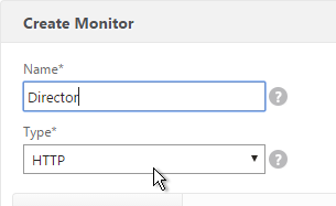
  3. Name it Director or similar.
  4. Change the Type drop-down to HTTP.
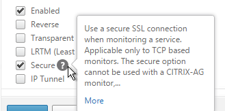
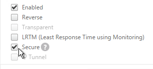
  5. If you will use SSL to communicate with the Director servers, then scroll down and check the box next to Secure.
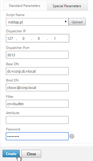
  6. Switch to the Special Parameters tab.
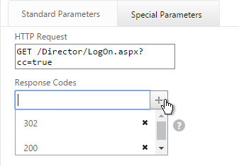
  7. In the HTTP Request field, enter GET /Director/LogOn.aspx?cc=true
  8. If Single Sign-on is enabled on Director, then you might have to add 302 as a Response Code.
  9. Click Create.

Servers

  1. On the left, expand Traffic Management, expand Load Balancing, and click Servers.
  2. On the right, click Add.
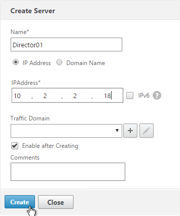
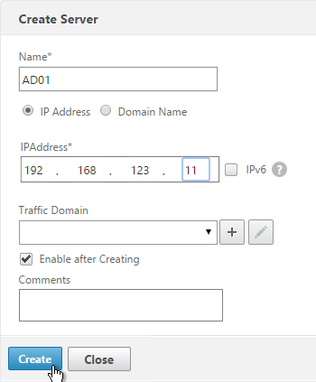
  3. Enter a descriptive server name. Usually it matches the actual server name.
  4. Enter the IP address of the server.
  5. Enter comments to describe the server. Click Create.
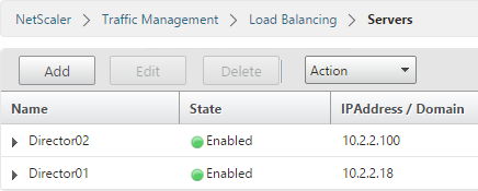
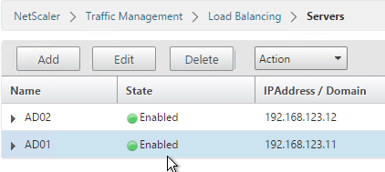
  6. Continue adding Director servers.

Service Group

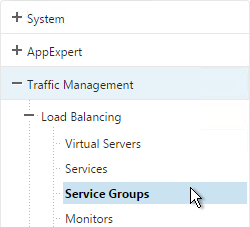
  1. On the left, expand Traffic Management, expand Load Balancing, and click Service Group.

  2. On the right, click Add.
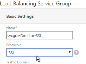
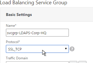
  3. Give the Service Group a descriptive name (e.g. svcgrp-Director-SSL).
  4. Change the Protocol to HTTP or SSL. If the protocol is SSL, ensure the Director Monitor has Secure enabled.
  5. Scroll down and click OK.
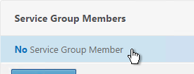
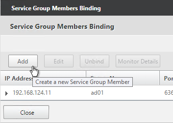
  6. Click where it says No Service Group Member.
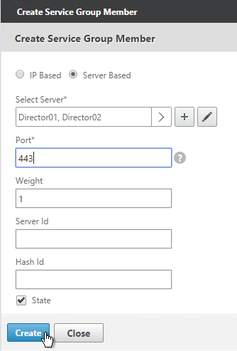
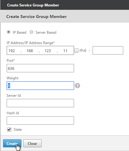
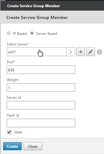
  7. If you did not previously create server objects, then enter the IP address of a Director Server. If you previously created a server objects, then change the selection to Server Based and select the server objects.
  8. Enter 80 or 443 as the port. Then click Create.
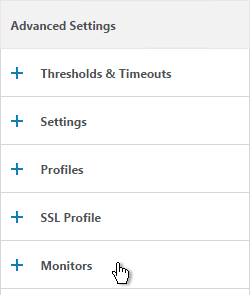
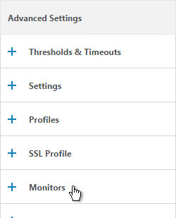
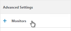
  9. On the right, under Advanced Settings, click Monitors.
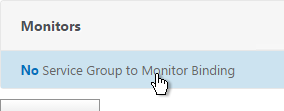
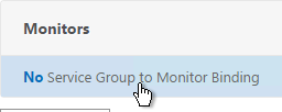
  10. On the left, in the Monitors section, click where it says No Service Group to Monitor Binding.
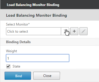
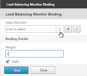
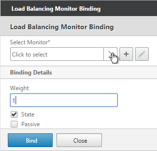
  11. Click the arrow next to Click to select.
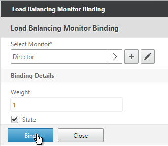
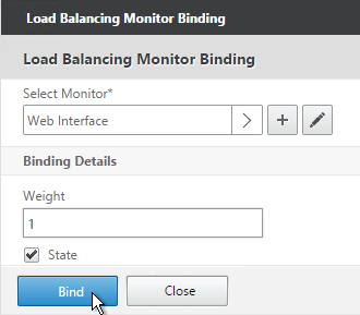
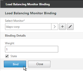
  12. Select the Director monitor and click Select.
  13. Then click Bind.
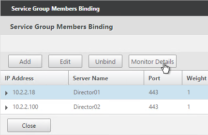
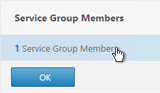
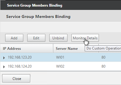
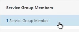
  14. To verify that the monitor is working, on the left, in the Service Group Members section, click the Service Group Members line.
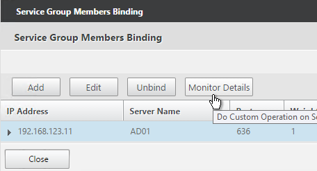
  15. Highlight a member and click Monitor Details.
  16. The Last Response should be Success – HTTP response code 200 received. Click Close twice.
  17. Then click Done.

Responder

Create a Responder policy to redirect users from the root page to /Director.

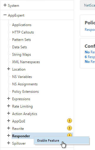
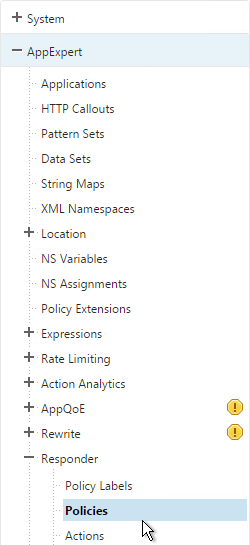
  1. Go to AppExpert > Responder and enable the feature if it isn’t already enabled.
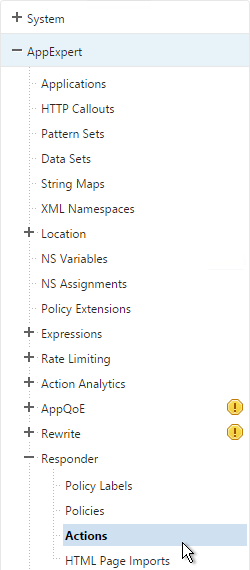
  2. Go to AppExpert > Responder > Actions.
  3. On the right, click Add.
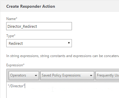
  4. Give the Action a name (e.g. Director_Redirect).
  5. Change the Type to Redirect.
  6. In the Expression box, enter "/Director", including the quotes.
  7. Click Create.
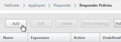
  8. Go to AppExpert > Responder > Policies.
  9. On the right, click Add.
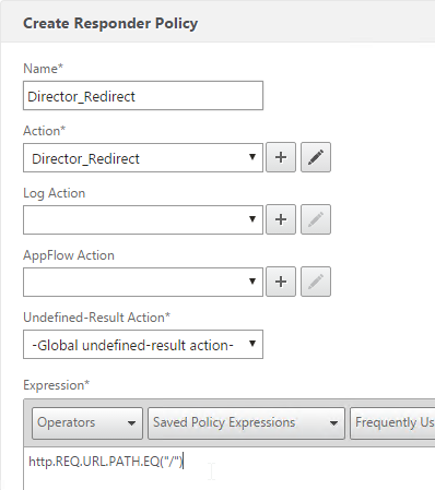
  10. Give the Policy a name (e.g. Director_Redirect).
  11. Select the previously created Action.
  12. In the Expression box, enter HTTP.REQ.URL.PATH.EQ("/")
  13. Click Create.

Load Balancing Virtual Server

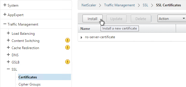
  1. Create or install a certificate that will be used by the SSL Virtual Server. This certificate must match the DNS name for the load balanced Director servers.
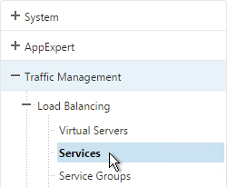
  2. On the left, under Traffic Management > Load Balancing, click Virtual Servers.

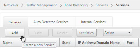
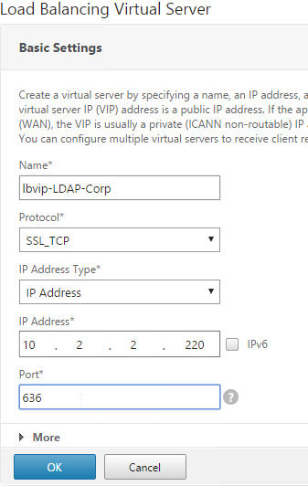
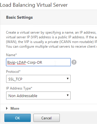
  3. On the right click Add.
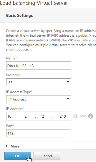
  4. Name it Director-SSL-LB or similar.
  5. Change the Protocol to SSL.
  6. Specify a new internal VIP.
  7. Enter 443 as the Port.
  8. Click OK.
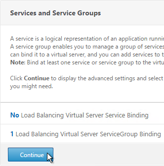
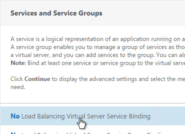
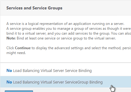
  9. On the left, in the Services and Service Groups section, click where it says No Load Balancing Virtual Server ServiceGroup Binding.
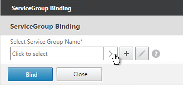
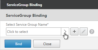
  10. Click the arrow next to Click to select.
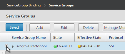
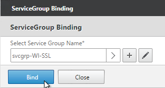
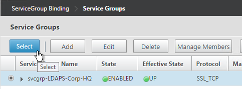
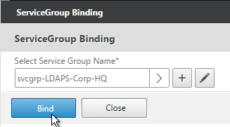
  11. Select your Director Service Group and click Select.
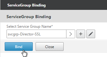
  12. Click Bind.
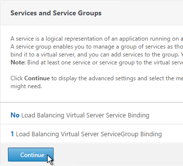
  13. Click Continue.
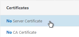
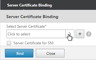
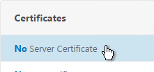
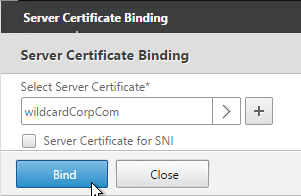
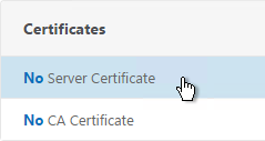
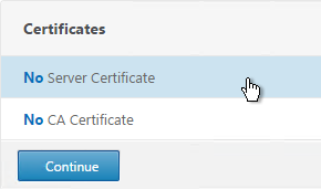
  14. Click where it says No Server Certificate.
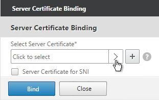
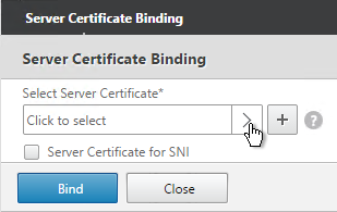
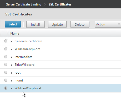
  15. Click the arrow next to Click to select.
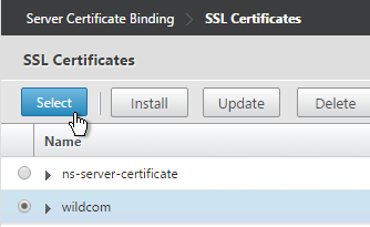
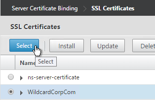
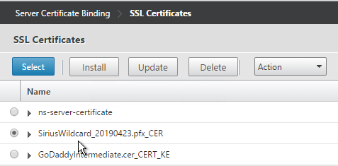
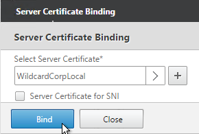
  16. Select the certificate for this Director Load Balancing Virtual Server and click Select.
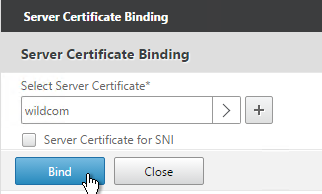
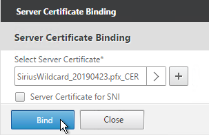
  17. Click Bind.
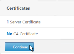
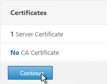
  18. Click Continue.
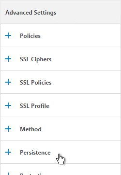
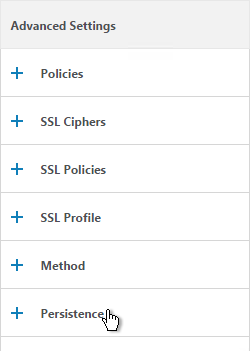
  19. On the right, in the Advanced Settings column, click Persistence.
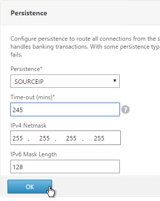
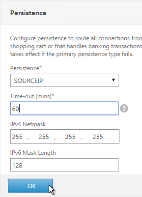
  20. Select SOURCEIP persistence.
  21. Set the timeout to match the timeout of Director. The default timeout for Director is 245 minutes.
  22. The IPv4 Netmask should default to 32 bits.
  23. Click OK.
  24. On the right, in the Advanced Settings section, add the Policies section.
  25. On the left, in the Policies section, click the plus icon.
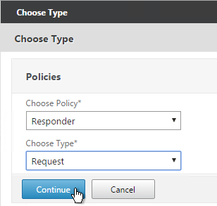
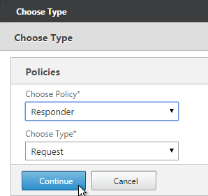
  26. Select Responder in the Choose Policy drop-down and click Continue.
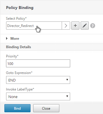
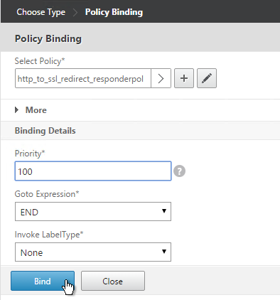
  27. Select the previously created Director_Redirect policy and click Bind.
  28. If you haven’t enabled the Default SSL Profile, then perform other normal SSL configuration including: disable SSLv3, bind a Modern Cipher Group, and enable Strict Transport Security.
    bind ssl vserver MyvServer -certkeyName MyCert
    
    set ssl vserver MyvServer -ssl3 DISABLED -tls11 ENABLED -tls12 ENABLED
    
    unbind ssl vserver MyvServer -cipherName ALL
    
    bind ssl vserver MyvServer -cipherName Modern
    
    bind ssl vserver MyvServer -eccCurveName ALL
    
    bind lb vserver MyvServer -policyName insert_STS_header -priority 100 -gotoPriorityExpression END -type RESPONSE

SSL Redirect

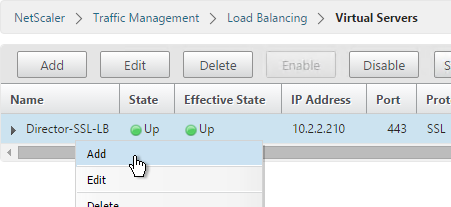
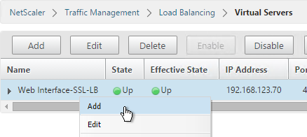
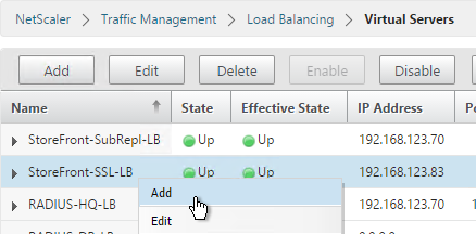
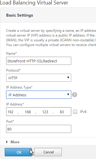
  1. Right-click the Director SSL Load Balancing Virtual Server and click Add.
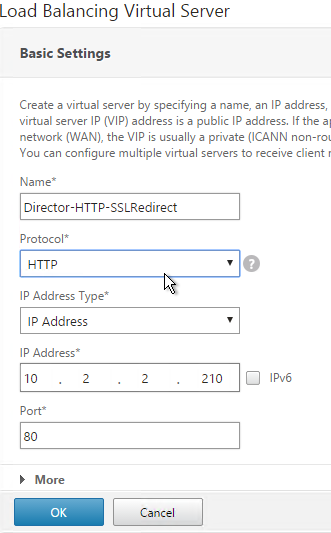
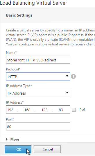
  2. Change the Name to Director-HTTP-SSLRedirect or something like that.
  3. Change the Protocol to HTTP.
  4. Click OK. This HTTP Virtual Server uses the same VIP as the SSL Load Balancer.
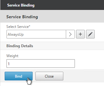
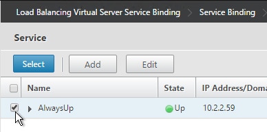
  5. Bind the AlwaysUp service. See SSL Redirect – Responder Method for more information.
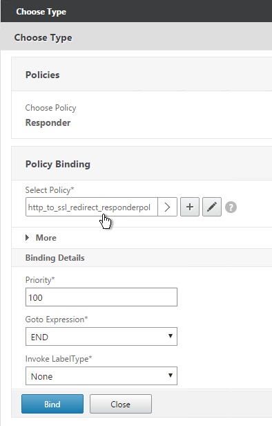
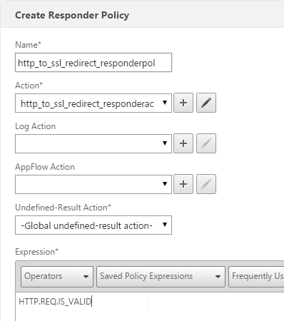
  6. Bind the http_to_ssl_redirect_responderpol Responder Policy.
  7. That’s all this LB vServer needs. Click Done when done.

SSL Warning

  1. If you are doing SSL Offload (SSL on front end, HTTP on back end), when connecting to Director it might complain about “You are not using a secure connection”.
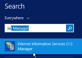
  2. To turn off this warning, login to the Director servers and run IIS Manager.
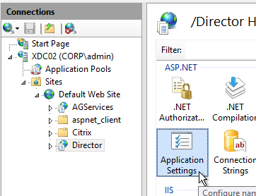
  3. On the left, navigate to Server > Sites > Default Web Site > Director.
  4. In the middle, double-click Application Settings.
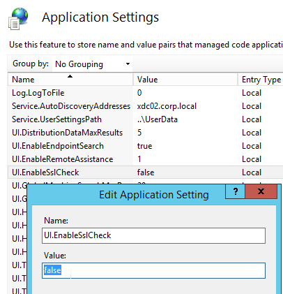
  5. Change UI.EnableSslCheck to false.

CLI Commands

Here is a list of NetScaler CLI commands for Director Load Balancing:

add server Director01 10.2.2.18
add server Director02 10.2.2.100
add server 127.0.0.1 127.0.0.1
add service AlwaysUp 127.0.0.1 HTTP 80
add serviceGroup svcgrp-Director-HTTP HTTP
add ssl certKey wildcom -cert WildcardCorpCom_pem -key WildcardCorpCom_pem
add lb vserver Director-SSL-LB SSL 10.2.2.210 443 -persistenceType SOURCEIP -timeout 245
add lb vserver Director-HTTP-SSLRedirect HTTP 10.2.2.210 80 -persistenceType NONE
add responder action Director_Redirect redirect "\"/Director\"" -responseStatusCode 302
add responder action http_to_ssl_redirect_responderact redirect "\"https://\" + HTTP.REQ.HOSTNAME.HTTP_URL_SAFE + HTTP.REQ.URL.PATH_AND_QUERY.HTTP_URL_SAFE" -responseStatusCode 302
add responder policy Director_Redirect "http.REQ.URL.PATH.EQ(\"/\")" Director_Redirect
add responder policy http_to_ssl_redirect_responderpol HTTP.REQ.IS_VALID http_to_ssl_redirect_responderact
bind lb vserver Director-HTTP-SSLRedirect AlwaysUp
bind lb vserver Director-SSL-LB svcgrp-Director-SSL
bind lb vserver Director-SSL-LB -policyName Director_Redirect -priority 100 -gotoPriorityExpression END -type REQUEST
bind lb vserver Director-HTTP-SSLRedirect -policyName http_to_ssl_redirect_responderpol -priority 100 -gotoPriorityExpression END -type REQUEST
add lb monitor Director HTTP -respCode 200 -httpRequest "GET /Director/LogOn.aspx?cc=true" -LRTM DISABLED -secure YES
bind serviceGroup svcgrp-Director-SSL Director01 443
bind serviceGroup svcgrp-Director-SSL Director02 443
bind serviceGroup svcgrp-Director-SSL -monitorName Director
set ssl serviceGroup svcgrp-Director-SSL -tls11 DISABLED -tls12 DISABLED
bind ssl vserver Director-SSL-LB -certkeyName wildcom
bind ssl vserver Director-SSL-LB -eccCurveName P_256
bind ssl vserver Director-SSL-LB -eccCurveName P_384
bind ssl vserver Director-SSL-LB -eccCurveName P_224
bind ssl vserver Director-SSL-LB -eccCurveName P_521

Web Interface Load Balancing – NetScaler 11

Last Modified: Nov 6, 2020 @ 7:24 am

Navigation

This procedure is only needed if you are running Web Interface instead of StoreFront.

Monitor

  1. On the left, expand Traffic Management, expand Load Balancing, and click Monitors.
  2. On the right, click Add.
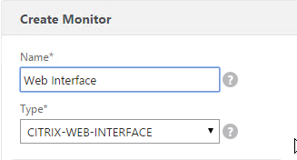
  3. Name it Web Interface or similar.
  4. Change the Type drop-down to CITRIX-WEB-INTERFACE.
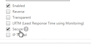
  5. If you will use SSL to communicate with the Web Interface servers, then scroll down and check the box next to Secure.
  6. Switch to the Special Parameters tab.
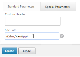
  7. In the Site Path field, enter the path of a XenApp Web site (e.g. /Citrix/XenApp/).
    • Make sure you include the slash (/) on the end of the path or else the monitor won’t work.
    • The site path is also case sensitive.
  8. Click Create.

Servers

  1. On the left, expand Traffic Management, expand Load Balancing, and click Servers.
  2. On the right, click Add.
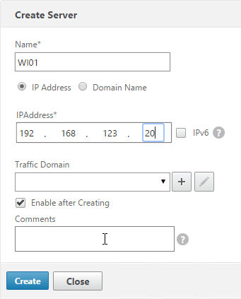
  3. Enter a descriptive server name, usually it matches the actual server name.
  4. Enter the IP address of the server.
  5. Enter comments to describe the server. Click Create.
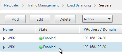
  6. Continue adding Web Interface servers.

Service Group

  1. On the left, expand Traffic Management, expand Load Balancing, and click Service Groups.

  2. On the right, click Add.
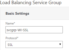
  3. Give the Service Group a descriptive name (e.g. svcgrp-WI-SSL).
  4. Change the Protocol to HTTP or SSL. If the protocol is SSL, ensure the Web Interface Monitor has Secure enabled.
  5. Scroll down and click OK.
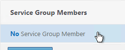
  6. Click where it says No Service Group Member.
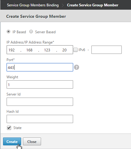
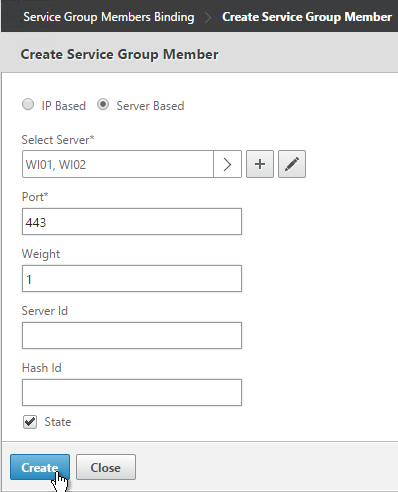
  7. If you did not create server objects then enter the IP address of a Web Interface Server. If you previously created a server object then change the selection to Server Based and select the server object.
  8. Enter 80 or 443 as the port. Then click Create.

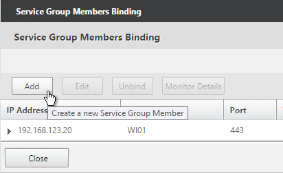
  9. To add more members, click where it says 1 Service Group Member and then click Add. Click Close when done.

  10. On the right, under Advanced Settings, click Monitors.
  11. On the left, in the Monitors section, click where it says No Service Group to Monitor Binding.
  12. Click the arrow next to Click to select.
  13. Select the Web Interface monitor and click Select.
  14. Then click Bind.
  15. To verify if the monitor is working or not, on the left, in the Service Group Members section, click the Service Group Members line.

  16. Highlight a member and click Monitor Details.
  17. The Last Response should indicate that Set-Cookie header was found. Click Close twice when done.
  18. Then click Done.

Load Balancing Virtual Server

  1. Create or install a certificate that will be used by the SSL Virtual Server. This certificate must match the DNS name for the load balanced Web Interface servers.
  2. On the left, under Traffic Management > Load Balancing, click Virtual Servers.

  3. On the right click Add.
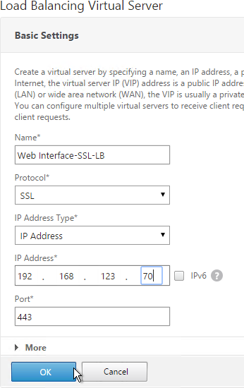
  4. Name it Web Interface-SSL-LB or similar.
  5. Change the Protocol to SSL.
  6. Specify a new internal VIP.
  7. Enter 443 as the Port.
  8. Click OK.
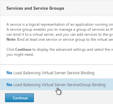
  9. On the left, in the Services and Service Groups section, click where it says No Load Balancing Virtual Server ServiceGroup Binding.
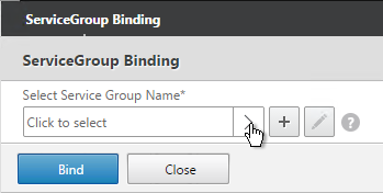
  10. Click the arrow next to Click to select.
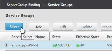
  11. Select your Web Interface Service Group and click Select.
  12. Click Bind.
  13. Click Continue.
  14. Click where it says No Server Certificate.
  15. Click the arrow next to Click to select.
  16. Select the certificate for this Web Interface Load Balancing Virtual Server and click Select.
  17. Click Bind.
  18. Click Continue.
  19. On the right, in the Advanced Settings column, click Persistence.
  20. Select SOURCEIP persistence. Note: COOKIEINSERT also works with Web Interface. However, it doesn’t work with StoreFront.
  21. Set the timeout to match the timeout of Web Interface.
  22. The IPv4 Netmask should default to 32 bits.
  23. Click OK.
  24. If you haven’t enabled the Default SSL Profile, then perform other normal SSL configuration including: disable SSLv3, bind a Modern Cipher Group, and enable Strict Transport Security.
    bind ssl vserver MyvServer -certkeyName MyCert
    
    set ssl vserver MyvServer -ssl3 DISABLED -tls11 ENABLED -tls12 ENABLED
    
    unbind ssl vserver MyvServer -cipherName ALL
    
    bind ssl vserver MyvServer -cipherName Modern
    
    bind ssl vserver MyvServer -eccCurveName ALL
    
    bind lb vserver MyvServer -policyName insert_STS_header -priority 100 -gotoPriorityExpression END -type RESPONSE

SSL Redirect – Down vServer Method

If you created an SSL Virtual Server that only listens on SSL 443, users must enter https:// when navigating to the website. To make it easier for the users, create another load balancing Virtual Server on the same VIP that listens on HTTP 80 and then redirects the user’s browser to reconnect on SSL 443. This section details the Down vServer method. Alternatively you can configure the Responder method.

  1. On the left, under Traffic Management > Load Balancing, click Virtual Servers.

  2. On the right, find the SSL Virtual Server you’ve already created, right-click it and click Add. Doing it this way copies some of the data from the already created Virtual Server.
  3. Change the name to indicate that this new Virtual Server is an SSL Redirect.
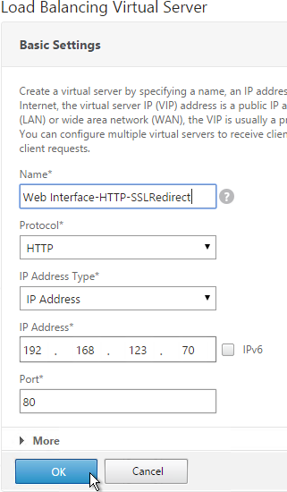
  4. Change the Protocol to HTTP on Port 80.
  5. The IP Address should already be filled in. It must match the original SSL Virtual Server. Click OK.
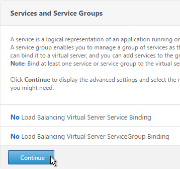
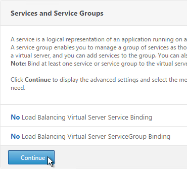
  6. Don’t select any services. This vServer must intentionally be marked down so the redirect will take effect. Click Continue.
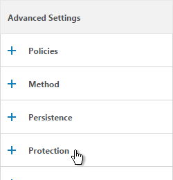
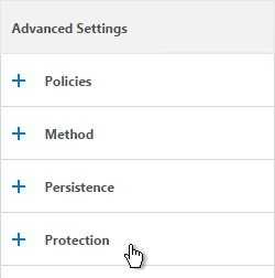
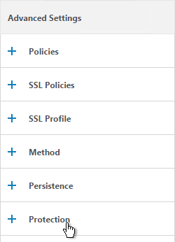
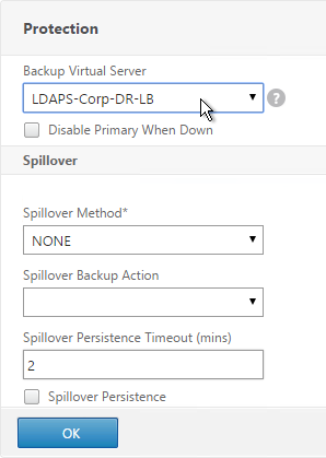
  7. On the right, in the Advanced Settings column, click Protection.
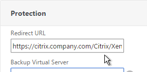
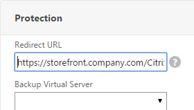
  8. In the Redirect URL field, enter the full URL including https://. For example: https://citrix.company.com/Citrix/XenApp. Click OK.
  9. Click Done.
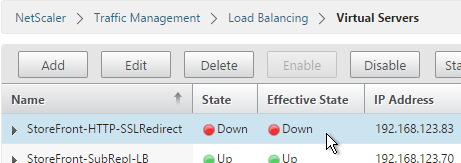
  10. When you view the SSL redirect Virtual Server in the list, it will have a state of DOWN. That’s OK. The Port 80 Virtual Server must be DOWN for the redirect to work.

Global Server Load Balancing (GSLB) – NetScaler 11

Last Modified: Nov 7, 2020 @ 6:34 am

Navigation

💡 = Recently Updated

GSLB Planning

GSLB is nothing more than DNS. GSLB is not in the data path. GSLB receives a DNS query and GSLB sends back an IP address, which is exactly how a DNS server works. However, GSLB can do some things that DNS servers can’t do:

  • Don’t give out an IP address unless it is UP (monitoring)
    • If active IP address is down, give out the passive IP address (active/passive)
  • Give out the IP address that is closest to the user (proximity load balancing)
  • Give out different IPs for internal vs external (DNS View)

GSLB is only useful if you have a single DNS name that could resolve to two or more IP addresses. If there’s only one IP address then use normal DNS instead.

Citrix Blog Post Global Server Load Balancing: Part 1 explains how DNS queries work and how GSLB fits in.

Citrix has a good DNS and GSLB Primer.

When configuring GSLB, don’t forget to ask “where is the data?”. For XenApp/XenDesktop, DFS multi-master replication of user profiles is not supported so configure “home” sites for users. More information at Citrix Blog Post XenDesktop, GSLB & DR – Everything you think you know is probably wrong!

GSLB can be enabled both externally and internally. For external GSLB, configure it on the DMZ NetScaler appliances and expose it to the Internet. For internal GSLB, configure it on internal NetScaler appliances. Note: Each NetScaler appliance only has one DNS table so if you try to use one NetScaler for both public and internal then be aware that external users can query for internal GSLB-enabled DNS names. As described by Phil Bossman in the comments, you can use a Responder policy to prevent external users from reading internal DNS names.  💡

add policy patset GSLB_INTERNAL
bind policy patset GSLB_INTERNAL internalHostname.gslb.domain.com -index 1
add responder action DNS_Empty_Response respondwith DNS.NEW_RESPONSE
add responder policy GSLB_DNS_Empty_Response "(!(CLIENT.IP.SRC.IN_SUBNET(10.0.0.0/8)||CLIENT.IP.SRC.IN_SUBNET(192.0.0.0/16)||CLIENT.IP.SRC.IN_SUBNET(172.0.0.0/12)) && DNS.REQ.QUESTION.DOMAIN.CONTAINS_ANY(\"GSLB_INTERNAL\"))" DNS_Empty_Response
bind responder global GSLB_DNS_Empty_Response 100 END -type DNS_REQ_DEFAULT

For internal and external GSLB of the same DNS name on the same appliance, you can use DNS Policies and DNS Views to return different IP addresses depending on where users are connecting from. Citrix CTX130163 How to Configure a GSLB Setup for Internal and External Users Using the Same Host Name.

However, GSLB monitoring applies to the entire GSLB Service so it would take down both internal and external GSLB. If you need different GSLB monitoring for internal and external of the same DNS name, try CNAME:

  • External citrix.company.com:
    • Configure NetScaler GSLB for citrix.company.com.
    • On public DNS, delegate citrix.company.com to the NetScaler DMZ ADNS services.
  • Internal citrix.company.com:
    • Configure NetScaler GSLB for citrixinternal.company.com or something like that.
    • On internal DNS, create CNAME for citrix.company.com to citrixinternal.company.com
    • On internal DNS, delegate citrixinternal.company.com to NetScaler internal ADNS services.


Some IP Addresses are needed on each NetScaler pair:

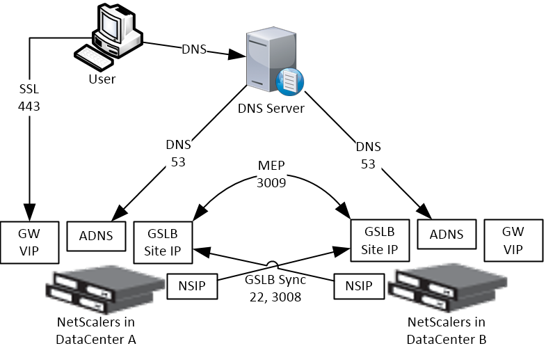
  • ADNS IP: An IP that will listen for ADNS queries. For external, create a public IP for the ADNS IP and open UDP 53 so Internet-based DNS servers can access it. This can be an existing SNIP on the appliance.
  • GSLB Site IP / MEP IP: A GSLB Site IP that will be used for NetScaler-to-NetScaler communication, which is called MEP or Metric Exchange Protocol. The IP for ADNS can also be used for MEP / GSLB Site.
    • RPC Source IP: If running NetScaler 11.0 build 64 or newer then the GSLB Site IP can be anything and RPC traffic (MEP) can be sourced from the GSLB IP. For older NetScaler builds, RPC traffic is sourced from a SNIP, even if this is different than the GSLB Site IP. In older builds, it’s less confusing if you use a SNIP as the GSLB Site IP.
    • Public IP: For external GSLB, create public IPs that are NAT’d to the GSLB Site IPs. The same public IP used for ADNS can also be used for MEP. MEP should be routed across the Internet so NetScaler can determine if the remote datacenter has Internet connectivity or not.
    • MEP Port: Open port TCP 3009 between the two NetScaler GSLB Site IPs. Make sure only the NetScalers can access this port on the other NetScaler. Do not allow any other device on the Internet to access this port. This port is encrypted.
    • GSLB Sync Ports: To use GSLB Configuration Sync, open ports TCP 22 and TCP 3008 from the NSIP (management IP) to the remote public IP that is NAT’d to the GSLB Site IP. The GSLB Sync command runs a script in BSD shell and thus NSIP is always the Source IP.
  • DNS Queries: The purpose of GSLB is to resolve a DNS name to one of several potential IP addresses. These IP addresses are usually public IPs that are NAT’d to existing Load Balancing, SSL Offload, Content Switching, or NetScaler Gateway VIPs in each datacenter.
  • IP Summary: In summary, for external GSLB, you will need a minimum of two public IPs in each datacenter:
    • One public IP that is NAT’d to the IP that is used for ADNS and MEP (GSLB Site IP). You only need one IP for ADNS / MEP no matter how many GSLB names are configured. MEP (GSLB Site IP) can be a different IP, if desired.
    • One public IP that is NAT’d to a Load Balancing, SSL Offload, Content Switching, or NetScaler Gateway VIP.
    • If you GSLB-enable multiple DNS names, each DNS name usually resolves to different IPs. This usually means that you will need additional public IPs NAT’d to additional VIPs.

ADNS

  1. Identify an NetScaler-owned IP that you will use for ADNS. This is typically a SNIP.
  2. Configure a public IP for the ANDS Service IP and configure firewall rules.
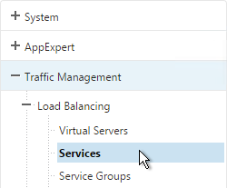
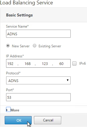
  3. On the left, expand Load Balancing and click Services.
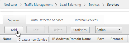
  4. On the right, click Add.
  5. Name the service ADNS or similar.
  6. In the IP Address field, enter an appliance SNIP.
  7. In the Protocol field, select ADNS. Then click OK.
  8. Scroll down and click Done.
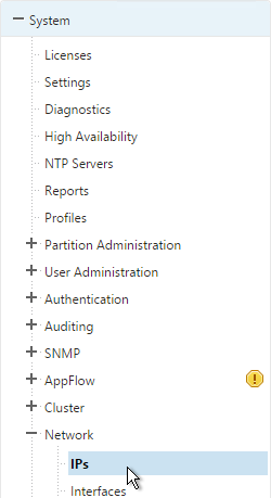
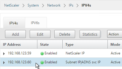
  9. On the left of the console, expand System, expand Network and then click IPs.
  10. On the right, you’ll see the SNIP as now being marked as the ADNS svc IP. If you don’t see this yet, click the Refresh icon.
  11. Repeat on the other appliance in the other datacenter.

Metric Exchange Protocol

  1. Select an IP to be the GSLB Site IP. In NetScaler 11.0 build 64 and newer, this can be any IP. In older builds, you can use the same SNIP and same public IP used for ADNS.
  2. Open the firewall rules for Metric Exchange Protocol.
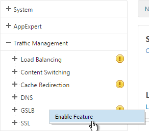
  3. On the left, expand Traffic Management, right-click GSLB and enable the feature.
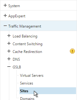
  4. Expand GSLB and click Sites.
  5. On the right, click Add.
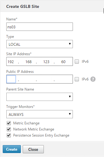
  6. Add the local site first. Enter a descriptive name and in the Site Type select LOCAL.
  7. In the Site IP Address field, enter an IP that this appliance will listen for MEP traffic. This IP must be in the default Traffic Domain. (Note: NetScaler 11.0 build 64 supports GSLB in Admin Partitions).
  8. For external GSLB, in the Public IP Address field, enter the public IP that is NAT’d to the GSLB Site IP. For internal GSLB, there’s no need to enter anything in the Public IP field. Click Create.
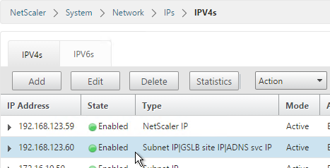
  9. Go back to System > Network > IPs and verify that the IP is now marked as a GSLB site IP. If you don’t see it yet, click the Refresh button.
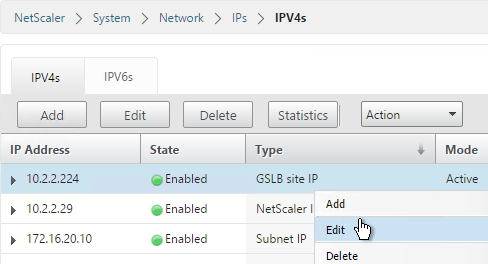
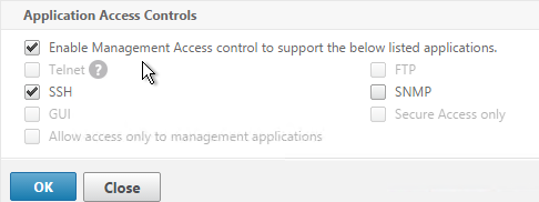
  10. If you want to use the GLSB Sync Config feature, then you’ll need to edit the GSLB site IP and enable Management Access.
  11. When you enable Management Access on a dedicated GSLB site IP, SSH is already selected by default. That’s all you need.
  12. Go to the other appliance and also create the local GSLB site using its GSLB site IP and its public IP that is NAT’d to the GSLB site IP.
  13. In System > Network > IPs on the remote appliance, there should now be a GSLB site IP. This could be a SNIP. If GSLB Sync is desired, enable management access on that IP and ensure SSH is enabled.
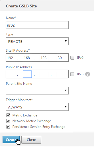
  14. Now on each appliance add another GSLB Site, which will be the remote GSLB site.
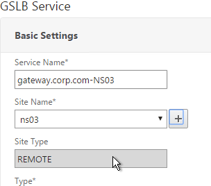
  15. Enter a descriptive name and select REMOTE as the Site Type.
  16. Enter the other appliance’s actual GSLB Site IP as configured on the appliance. This IP does not need to be reachable.
  17. In the Public IP field, enter the public IP that is NAT’d to the GSLB Site IP on the other appliance. For MEP, TCP 3009 must be open to this IP from the local GSLB Site IP. For GSLB sync, TCP 22, and TCP 3008 must be open to this IP from the local NSIP. Click Create.
  18. Repeat on the other appliance.
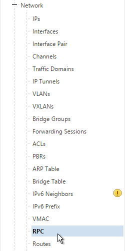
  19. MEP will not function yet since the NetScalers are currently configured to communicate unencrypted on TCP 3011. To fix that, on the left, expand System, expand Network and click RPC.
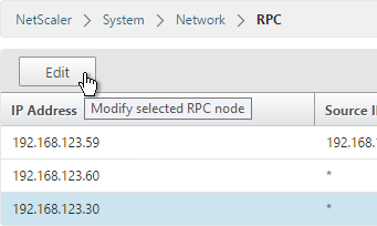
  20. On the right, edit the new RPC address (the other site’s GSLB Site IP) and click Open.
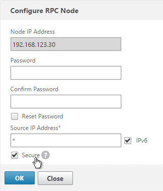
  21. On the bottom, check the box next to Secure.
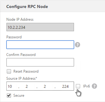
  22. In NetScaler 11.0 build 64 or newer, if your GSLB Site IP is not a SNIP then you’ll need to change the RPC Node to use the local GSLB Site IP as the source IP. Uncheck IPv6 first. Then enter the local GSLB Site IP. Click OK when done.
  23. Do the same thing on the other appliance.
  24. If you go back to GSLB > Sites, you should see it as active.

GSLB Services

GSLB Services represent the IP addresses that are returned in DNS Responses. DNS Query = DNS name. DNS Response = IP address.

GSLB should be configured identically on both NetScalers. Since you have no control over which NetScaler will receive the DNS query, you must ensure that both NetScalers are giving out the same DNS responses.

Create the same GSLB Services on both NetScalers:

  1. Start on the appliance in the primary data center. This appliance should already have a traffic Virtual Server (NetScaler Gateway, Load Balancing, or Content Switching) for the DNS name that you are trying to GSLB enable.
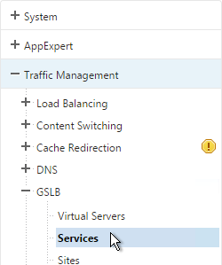
  2. On the left, expand Traffic Management > GSLB and click Services.
  3. On the right, click Add.
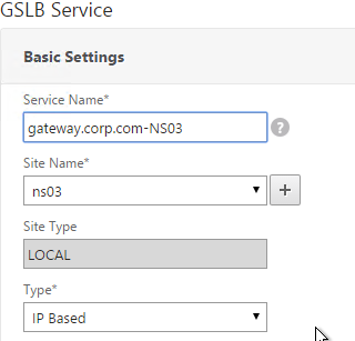
  4. The service name should be similar to the DNS name that you are trying to GSLB. Include the site name in the service name.
  5. Select the LOCAL Site.
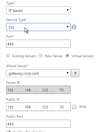
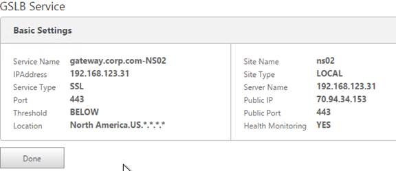
  6. On the bottom part, select Virtual Servers and then select a Virtual Server that is already defined on this appliance. It should automatically fill in the other fields. If you see a message asking if you wish to create a service object, click Yes.
  7. Scroll up and make sure the Service Type is SSL. It’s annoying that NetScaler doesn’t set this drop-down correctly.
  8. The Public IP field contains the actual IP Address that the GSLB ADNS service will hand out. Make sure this Public IP is user accessible. It doesn’t even need to be a NetScaler owned IP.
  9. Scroll down and click OK.
  10. If the GSLB Service IP is a VIP on the local appliance, then GSLB will simply use the state of the local traffic Virtual Server (Load Balancing, Content Switching, or Gateway). If the GSLB Service IP is a VIP on a remote appliance, then GSLB will use MEP to ask the other appliance for the state of the remote traffic Virtual Server. In both cases, there’s no need to bind a monitor to the GSLB Service.
  11. However, you can also bind monitors directly to the GSLB Service. Here are some reasons for doing so:
    • If the GSLB Service IP is a NetScaler-owned traffic VIP, but the monitors bound the traffic Virtual Server are not the same ones you want to use for GSLB. When you bind monitors to the GSLB Services, the monitors bound to the traffic Virtual Server are ignored.
    • If the GSLB Service IP is in a non-default Traffic Domain, then you will need to attach a monitor since GSLB cannot determine the state of Virtual Servers in non-default Traffic Domains.
    • If the GSLB Service IP is not hosted on a NetScaler, then only GSLB Service monitors can determine if the Service IP is up or not.
  12. If you intend to do GSLB active/active and if you need site persistence then you can configure your GSLB Services to use Connection Proxy or HTTP Redirect. See Citrix Blog Post Troubleshooting GSLB Persistence with Fiddler for more details.
  13. Click Done.
  14. On the other datacenter NetScaler, create a GSLB Service.
  15. Select the REMOTE site that is hosting the service.
  16. Since the service is on a different appliance and not this one, you won’t be able to select it using the Virtual Servers option. Instead, select New Server.
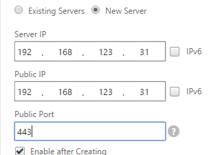
  17. For the Server IP, enter the actual VIP configured on the other appliance. This local NetScaler will use GSLB MEP to communicate with the remote NetScaler to find a traffic Virtual Server with this VIP. The remote NetScaler respond if the remote traffic Virtual Server is up or not. The remote Server IP configured here does not need to be directly reachable by this local appliance. If the Server IP is not owned by either NetScaler, then you will need to bind monitors to your GSLB Service.
  18. In the Public IP field, enter the IP address that will be handed out to clients. This is the IP address that users will use to connect to the service. For Public DNS, you enter a Public IP that is usually NAT’d to the traffic VIP. For internal DNS, the Public IP and the Server IP are usually the same.
  19. Scroll up and change the Service Type to match the Virtual Server defined on the other appliance..
  20. Click OK.
  21. Just like the other appliance, you can also configure Site Persistence and GSLB Service Monitors. Click Done when done.
  22. Create more GSLB Services, one for each traffic VIP. GSLB is useless if there’s only one IP address to return. You should have multiple IP addresses (VIPs) through which a web service (e.g. NetScaler Gateway) can be accessed. Each of these VIPs is typically in different datacenters, or on different Internet circuits. The mapping between DNS name and IP addresses is configured in the GSLB vServer, as detailed in the next section.

GSLB Virtual Server

The GSLB Virtual Server is the entity that the DNS name is bound to. GSLB vServer then gives out the IP address of one of the GSLB Services that is bound to it.

Configure the GSLB vServer identically on both appliances:

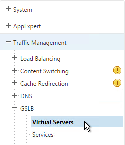
  1. On the left, expand Traffic Management > GLSB, and click Virtual Servers.
  2. On the right, click Add.
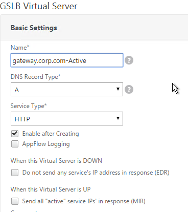
  3. Give the GSLB vServer a descriptive name. For active/active, you can name it the same as your DNS name. For active/passive, you will create two GSLB Virtual Servers, one for each datacenter, so include Active or Passive in the Virtual Server name.
  4. Click OK.
  5. If you intend to bind multiple GSLB Services to this GSLB vServer, then you can optionally check the box for Send all “active” service IPs. By default, GSLB only gives out one IP per DNS query. This checkbox always returns all IPs, but the IPs are ordered based on the GSLB Load Balancing Method and/or GSLB Persistence.
  6. On the right, in the Advanced Settings column, click Service.
  7. On the left, click where it says No GSLB Virtual Server to GSLBService Binding.
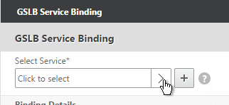
  8. Click the arrow next to Click to select.
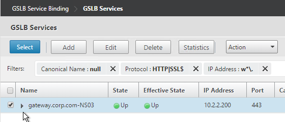
  9. Check the box next to an existing GSLB Service and click Select. If your GSLB is active/passive then only bind one service.
  10. If your GSLB is active/active then bind multiple GSLB Services. Also, you’d probably need to configure GSLB persistence (Source IP or cookies).
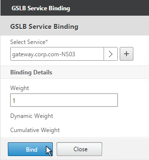
  11. Click Bind.
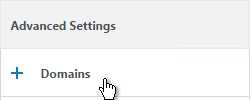
  12. On the right, in the Advanced Settings column, click Domains.
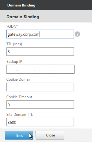
  13. On the left, click where it says No GSLB Virtual Server Domain Binding.
  14. Enter the FQDN that GSLB will resolve.
  15. If this GSLB is active/passive, there are two options:
    • Use the Backup IP field to specify the IP address that will be handed out if the primary NetScaler is inaccessible or if the VIP on the primary appliance is marked down for any reason.
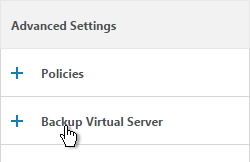
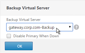
    • Or, create a second GSLB Virtual Server that has the passive GSLB service bound to it. Don’t bind a Domain to the second GSLB Virtual Server. Then edit the Active GSLB Virtual Server and use the Backup Virtual Server section to select the second GSLB Virtual Server.
  16. Click Bind.
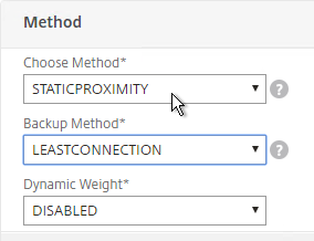
  17. If this is active/active GSLB, you can edit the Method section to enable Static Proximity. This assumes the Geo Location database has already been installed on the appliance.
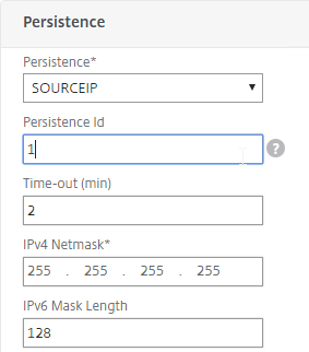
  18. Also for active/active, if you don’t want to use Cookie-based persistence, then you can use the Persistence section to configure Source IP persistence.
  19. Click Done.
  20. If you are configuring active/passive using the backup GSLB Virtual Server method, create a second GSLB Virtual Server that has the passive GSLB service bound to it. Don’t bind a Domain to the second GSLB Virtual Server. Then edit the Active GSLB Virtual Server and use the Backup Virtual Server section to select the second GSLB Virtual Server.

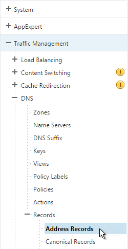
  21. On the left, if you expand Traffic ManagementDNS, expand Records and click Address Records, you’ll see a new DNS record for the GSLB domain you just configured. Notice it is marked as GSLB DOMAIN.

  22. Configure identical GSLB Virtual Servers on the other NetScaler appliance. Both NetScalers must be configured identically.
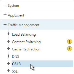
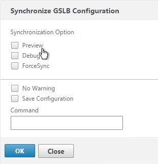
  23. You can also synchronize the GSLB configuration with the remote appliance by going to Traffic Management > GSLB.
  24. On the right, click Synchronize configuration on remote sites.
  25. Use the check boxes on the top, if desired. It’s usually a good idea to Preview the changes before applying them. Then click OK to begin synchronization.

Some notes regarding GSLB Sync:

  • It’s probably more reliable to do it from the CLI by running sync gslb config and one of the config options (e.g. -preview).
  • GSLB Sync runs as a script on the BSD shell and thus always uses the NSIP as the source IP.
  • GSLB Sync connects to the remote GSLB Site IP on TCP 3008 (if RPC is Secure) and TCP 22.

Test GSLB

  1. To test GSLB, simply point nslookup to the ADNS services and submit a DNS query for one of the DNS names bound to a GSLB vServer. Run the query multiple times to make sure you’re getting the response you expect.
  2. Both NetScaler ADNS services should be giving the same response.
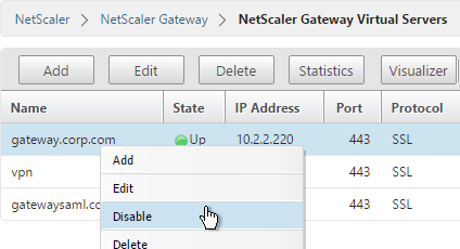
  3. To simulate a failure, disable the traffic Virtual Server.
  4. Then the responses should change. Verify on both ADNS services.

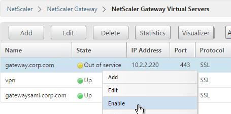
  5. Re-enable the traffic Virtual Server, and the responses should return to normal.


DNS Delegation

If you are enabling GSLB for the domain gateway.corp.com, you’ll need to create a delegation at the server that is hosting the corp.com DNS zone. For public GSLB, you need to edit the public DNS zone for corp.com.

DNS Delegation instructions will vary depending on what product host’s the public DNS zone. This section details Microsoft DNS, but it should be similar in BIND or web-based DNS products.

There are two ways to delegate GSLB-enabled DNS names to NetScaler ADNS:

  • Delegate the individual record. For example, delegate gateway.corp.com to the two NetScaler ADNS services (gslb1.corp.com and gslb2.corp.com).
  • Delegate an entire subzone. For example, delegate the subzone gslb.corp.com to the two NetScaler ADNS services. Then create a CNAME record in the parent DNS zone for gateway.corp.com that is aliased to gateway.gslb.corp.com. When DNS queries make it to NetScaler, they will be for gateway.gslb.corp.com and thus gateway.gslb.corp.com needs to be bound to the GSLB Virtual Server instead of gateway.corp.com. For additional delegations, simply create more CNAME records.

This section covers the first method – delegating an individual DNS record:

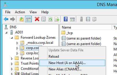
  1. Run DNS Manager.
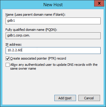
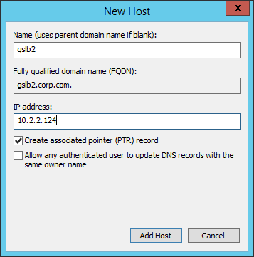
  2. First, create Host Records pointing to the ADNS services running on the NetScalers in each data center. These host records for ADNS are used for all GSLB delegations no matter how many GSLB delegations you need to create.
  3. The first Host record is gslb1 (or similar) and should point to the ADNS service (Public IP) on one of the NetScaler appliances.
  4. The second Host record is gslb2 and should point to the ADNS Service (public IP) on the other NetScaler appliance.
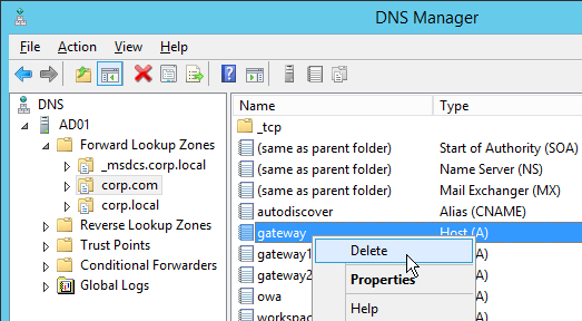
  5. If you currently have a host record for the service that you are delegating to GSLB (gateway.corp.com), delete it.
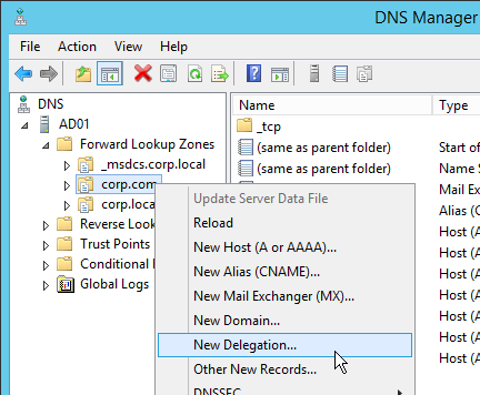
  6. Right-click the parent DNS zone and click New Delegation.
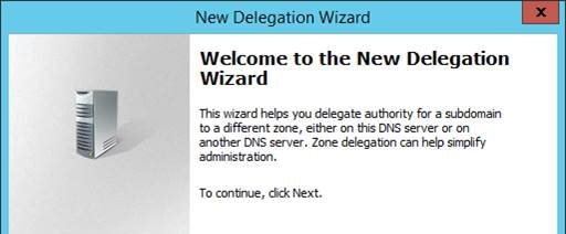
  7. In the Welcome to the New Delegation Wizard page, click Next.
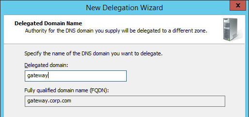
  8. In the Delegated Domain Name page, enter the left part of the DNS record that you are delegating (e.g. gateway). Click Next.
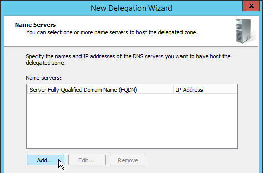
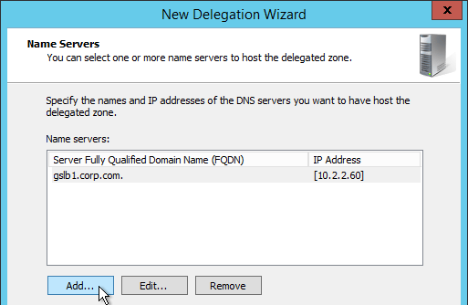
  9. In the Name Servers page, click Add.
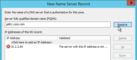
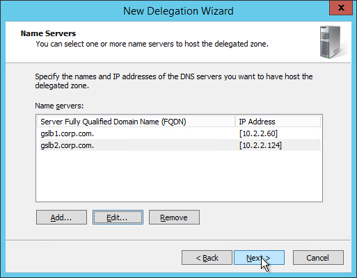
  10. This is where you specify gslb1.corp.com and gslb2.corp.com. Enter gslb1.corp.com and click Resolve. Then click OK. If you see a message about the server not being authoritative for the zone, ignore the message.
  11. Then click Add to add the other GSLB ADNS server.
  12. Once both ADNS servers are added to the list, click Next.
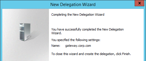
  13. In the Completing the New Delegation Wizard page, click Finish.
  14. If you run nslookup against your Microsoft DNS server, it will respond with Non-authoritative answer. That’s because it got the response from NetScaler and not from itself.

That’s all there is to it. Your NetScalers are now DNS servers. For active/passive, the NetScalers will hand out the public IP address of the primary data center. When the primary data center is not accessible, GSLB will hand out the GSLB Service IP bound to the Backup GSLB vServer.

Geo Location Database

If you want to use DNS Policies or Static Proximity GSLB Load Balancing or Responders based on user’s location, import a geo location database.

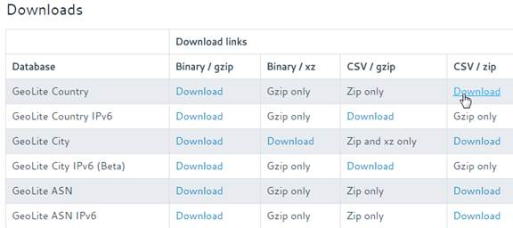
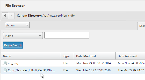
NetScaler 11 has a built-in database at /var/netscaler/inbuilt_db/ that you can use. Or you can download a database. Common free databases are:

For IP2Location, see the blog post Add IP2Location Database as NetScaler’s Location File for instructions on how to import.

To Download GeoLite Legacy:

  1. Download the GeoLite Country database CSV from http://dev.maxmind.com/geoip/legacy/geolite/.
  2. Note: GeoLite City is actually two files that must be merged as detailed at Citrix Blog Post GeoLite City as NetScaler location database. GeoLite Country doesn’t need any preparation.
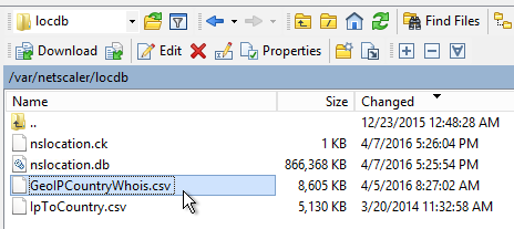
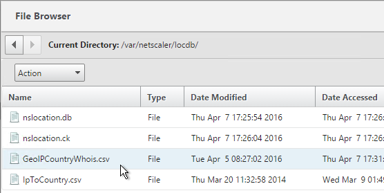
  3. Upload the extracted database (.csv file) to the NetScaler appliance at /var/netscaler/locdb.

To import the Geo database (including the built-in database):

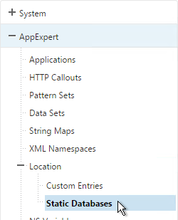
  1. In the NetScaler GUI, on the left, expand AppExpert, expand Location and click Static Database (IPv4).
  2. On the right, click Add.
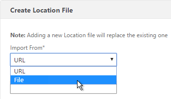
  3. Change the Import From selection to File.
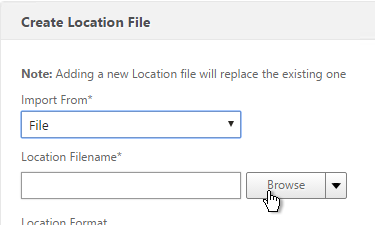
  4. Click Browse.
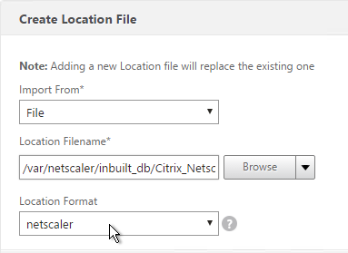
  5. For the built-in database, browse to /var/netscaler/inbuilt_db/ and open Citrix_NetScaler_InBuild_GeoIP_DB.csv.
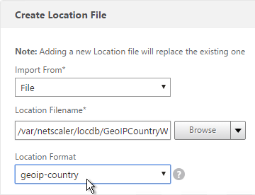
  6. Or browse to the Geo Location database file you uploaded and open it.
  7. In the Location Format field, if using the built-in database, select netscaler.
  8. If using GeoLite Country, select geoip-country.
  9. Click Create.
  10. When you open a GSLB Service, the public IP will be translated to a location.

You can use the Geo locations in a DNS Policy, static proximity GSLB Load Balancing, or Responders:

Horizon View Load Balancing – NetScaler 11

Last Modified: Sep 2, 2018 @ 7:52 am

Navigation

Use this procedure to load balance Horizon View Connection Servers, Horizon View Security Servers, and/or VMware Access Points.

Overview

Servers/Appliances

There are two VMware-provided remote access solutions for Horizon:

Access Points are preferred over Security Servers for the following reasons:

  • No need to pair with internal Connection Servers. This simplifies the configuration.
  • Linux appliance instead of Windows server.
  • Authentication can be offloaded to Access Point. This includes: Smart Cards, RSA, and RADIUS.

If you are using Access Points instead of Security Servers then you’ll have the following machines in a highly available Horizon infrastructure:

  • Two Internal Connection Servers – these need to be load balanced on an internal VIP. Internal users connect to the internal VIP.
  • Two DMZ Access Point appliances – these need to be load balanced on a DMZ VIP. External users connect to the DMZ VIP. Access Points connect to the internal VIP.
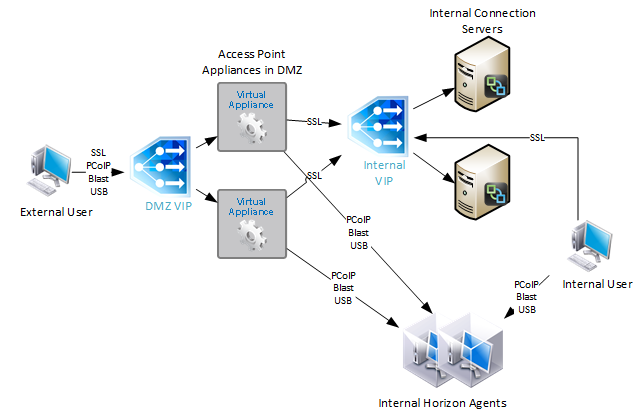
With Security Servers instead of Access Points, a typical Horizon Infrastructure will have at least six connection servers:

  • Two Internal Connection Servers – these need to be load balanced on an internal VIP. Internal users connect to the internal VIP.
  • Two DMZ Security Servers – these need to be load balanced on a DMZ VIP. External users connect to the DMZ VIP. Each Security Servers connects directly to a “paired” Connection Servers.
  • The DMZ Security Servers are paired with two additional internal “paired” Connection Servers. There is no need to load balance the internal Paired Connection Servers. However, we do need to monitor them.
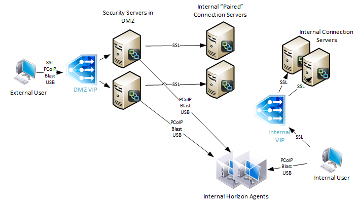
Since Security Servers are paired with Connection Servers, you need to configure load balancing monitors to disable the Security Server if the paired Connection Server is not accessible. Since Access Points are not paired with Connection Servers, you don’t need this special monitoring configuration.

Protocols/Ports

Horizon 7 introduces a new Blast Extreme protocol. VMware Technical White Paper Blast Extreme Display Protocol in Horizon 7.

For VMware Access Point, Blast Extreme only needs TCP and UDP 443 only. HTML Access in Horizon 7 also uses Blast Extreme protocol (TCP/UDP 443). If you use VMware Access Point with Blast Extreme exclusively, then the number of ports is minimal, and load balancing configuration is simplified. Here are typical load balancing port requirements for Access Point with Blast Extreme only:

  • TCP 443
  • UDP 443

Note: UDP is disabled by default, but it can be enabled using a Blast GPO setting.

For View Security Servers, and Blast Extreme protocol only, then the following load balancing ports are needed. Note: Access Point supports 443 port sharing, but Security Servers do not.

  • TCP 443
  • TCP 8443
  • UDP 8443

Note: UDP is disabled by default, but it can be enabled using a Blast GPO setting.

For all other configurations that don’t use Blast Extreme (PCoIP, HTML Blast), the following ports must be load balanced:

  • TCP 443
  • TCP 4172
  • UDP 4172
  • TCP 8443

If you are load balancing internal Connection Servers only, and if the Secure Gateways are disabled, then the only port you need to load balance is:

  • TCP 443

VMware requires server persistence to apply across multiple load balanced port numbers. If a user is load balanced to a particular View Connection Server on TCP 443, then the connection on UDP 4172 must go the same View Connection Server. Normally load balancing persistence only applies to a single port number, so whatever sever was selected on 443 won’t be considered for the 4172 connection. But in NetScaler, you can configure a Persistency Group to use a single persistency across multiple load balancing vServers (different port numbers). In F5, you configure Match Across.

Also see Load Balancing with Access Point by Mark Benson at VMware Communities  💡

This topic primarily focuses on NetScaler GUI configuration. Alternatively, you can skip directly to the CLI commands.

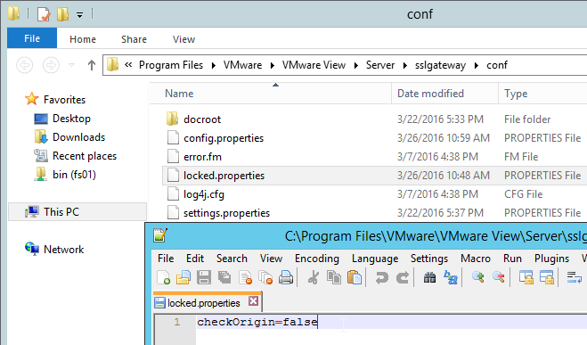
Horizon 7 Origin Check

Horizon 7 might not accept your load balanced DNS name unless it’s the same name configured in the Connection Server’s Secure Tunnel configuration. You can change this behavior by disabling Origin Check as detailed at VMware 2144768 Accessing the Horizon View Administrator page displays a blank error window in Horizon 7. Note: this configuration is almost mandatory for Access Points since Secure Tunnel is disabled on the Connection Servers.
Load Balancing Monitors

Users connect to Connection Servers, Security Servers, and Access Point appliances on multiple ports: TCP 443, UDP 443, TCP 8443, UDP 8443, TCP 4172, and UDP 4172. Users will initially connect to TCP port 443 and then be redirected to one of the other ports on the same server/appliance initially used for the TCP 443 connection. If TCP 443 is up but UDP 4172 is down on the same server/appliance then you probably wan’t to take TCP 443 down too. To facilitate this, create a monitor for each of the ports and bind all of the monitors to the TCP 443 service. Then if any of the monitors goes down then TCP 443 is also take down.

Note: TLS 1.0 is disabled in Horizon View 6.2.1 and newer. If your NetScaler supports TLS 1.2 on the back end then this isn’t a problem. Back-end TLS 1.2 was added to NetScaler MPX/SDX in 10.5 build 58. And it was added to NetScaler VPX in 11.0 build 65. For older NetScaler builds, you’ll need to enable TLS 1.0 (and HTML Blast) in Horizon or else the monitors won’t work.

In NetScaler VPX 11.0 build 64, secure HTTP monitors attached to SSL_BRIDGE services try to use TLS 1.2 instead of TLS 1.0. To fix this problem, run set ssl parameter -svctls1112disable enable -montls1112disable enable as detailed at CTX205578 Back-End Connection on TLS 1.1/1.2 from NetScaler to IIS Servers Break.

SSL Monitor

  1. On the left, expand Traffic Management, expand Load Balancing, and click Monitors.
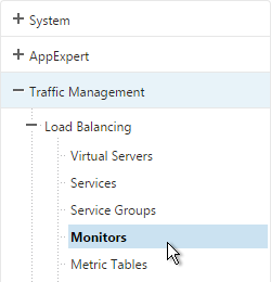
  2. On the right, click Add.
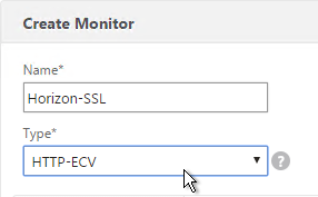
  3. Name it Horizon-SSL or similar.
  4. Change the Type drop-down to HTTP-ECV.
  5. On the Standard Parameters tab, in the Destination Port field, enter 443.
  6. Scroll down and check the box next to Secure.
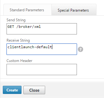
  7. On the Special Parameters tab, in the Send String section, enter GET /broker/xml
  8. In the Receive String section, enter clientlaunch-default
  9. Scroll down and click Create.

PCoIP Monitor

  1. On the right, click Add.
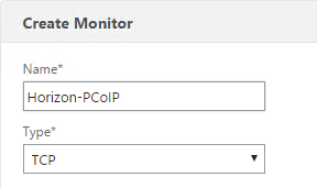
  2. Name it Horizon-PCoIP or similar.
  3. Change the Type drop-down to TCP.
  4. On the Standard Parameters tab, in the Destination Port field, enter 4172.
  5. Scroll down and click Create.

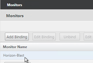
Blast Monitor

  1. On the right, click Add.
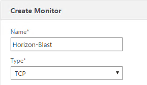
  2. Name it Horizon-Blast or similar.
  3. Change the Type drop-down to TCP.
  4. On the Standard Parameters tab, in the Destination Port field, enter 8443.
  5. Scroll down and click Create.

Paired Connection Server Monitor

Note: the steps in this section do not apply to Access Points or internal Connection Servers.

View Security Servers are paired with View Connection Servers. If the paired View Connection Server is down, then we should probably stop sending users to the corresponding View Security Server. Let’s create a monitor that has a specific IP address in it.

  1. Right-click the existing Horizon-SSL monitor and click Add.
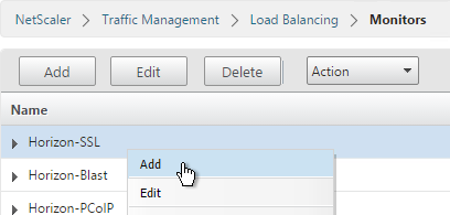
  2. Normally a monitor does not have any Destination IP defined, which means it uses the IP address of the service that it is bound to. However, we intend to bind this monitor to the View Security Server but we need it to monitor the paired View Connection Server, which is a different IP address. Type in the IP address of the paired View Connection Server. Then rename the monitor so it includes the View Connection Server name. Click Create.
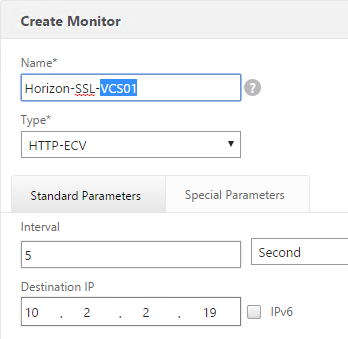
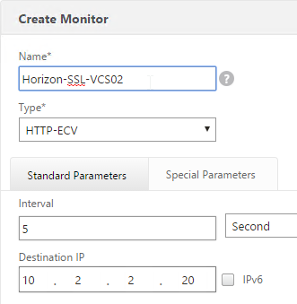
  3. Since we are embedding an IP address into the monitor, you have to create a separate monitor for each paired Connection Server IP. Create another monitor. Specify the IP of the other paired Connection Server. Click Create.
Load Balancing Servers

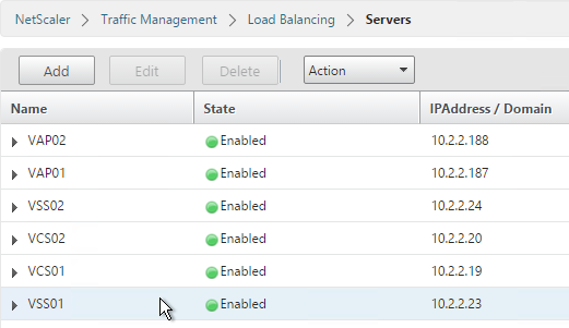
Create Server Objects for the DMZ Security Servers, DMZ Access Point appliances and the internal non-paired Connection Servers. Do not create Server Objects for the Paired Connection Servers.

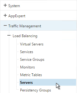
  1. On the left, expand Traffic Management, expand Load Balancing, and click Servers.
  2. On the right, click Add.
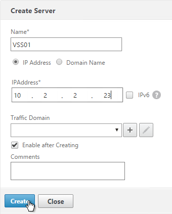
  3. Enter a descriptive server name, usually it matches the actual server name.
  4. Enter the IP address of the Access Point, Horizon Connection Server, or Horizon Security Server.
  5. Enter comments to describe the server. Click Create.
  6. Continue adding Access Points, Horizon Connection Servers, and/or Horizon Security Servers.
Load Balancing Services

Overview

Services vs Service Groups:

  • For Security Servers, if the paired Connection Server is down, then we need the Security Server to go down too. One of the monitors bound to the Security Server contains the IP address of the paired Connection Server. Since each Security Server is paired with a different Connection Server, that means each Security Server will have a unique monitoring configuration. This precludes us from adding multiple Security Servers to a single Service Group since you can only have one monitor configuration for the entire Service Group. Instead, create separate Services (multiple port numbers) for each Security Server.
    • Individual services per server are only needed for TCP 443. The other ports can be service groups.
  • For Access Points, there is no special monitoring configuration and thus these appliances could be added to Service Groups (one for each port number).
  • For internal Connection Servers (non-paired), there is no special monitoring configuration and thus these appliances could be added to one Service Group. Internal Connection Servers usually only need TCP 443 load balanced.

For Internal Connection Servers (not the paired servers), load balancing monitoring is very simple:

  • Create a service group for SSL 443.
  • To verify server availability, monitor port TCP 443 on the same server.
  • If tunneling is disabled then internal users connect directly to View Agents and UDP/TCP 4172 and TCP 8443 are not used on Internal Connection Servers. There’s no need to create service groups and monitors for these ports.

Security Servers and Access Point appliances are more complex:

  • For Blast Extreme protocol through Access Points, if UDP is not enabled, then you only need services for TCP 443. If UDP is enabled, then you also need load balancing services for UDP 443.
  • For Blast Extreme protocol through View Security Servers, if UDP is not enabled, then you only need services for TCP 443 and TCP 8443. If UDP is enabled, then you also need load balancing services for UDP 8443.
  • For PCoIP protocol, all traffic initially connects on TCP 443. The Horizon clients then connect to UDP 4172 on the same Security Server or Access Point. If 4172 is down, then 443 should be taken down. Bind monitors for each port to the TCP 443 service. If any of the monitors fails (e.g. 4172 is down), then TCP 443 is taken down and NetScaler will no longer forward traffic to TCP 443 on that particular server/appliance.
  • Each Security Server is paired with an internal Connection Server. If the internal Connection Server is down then the Security Server should be taken down. This requires custom monitors for each Security Server. This is not a problem for Access Points.

Load Balancing Services Configuration Summary

The summaries are split into PCoIP vs Blast Extreme, and View Security Servers vs Access Points. If you are using both PCoIP and Blast Extreme, combine their configurations.

Two Access Points for Blast Extreme: if they are named VAP01 and VAP02, the load balancing service configuration for Blast Extreme in Horizon 7 (no PCoIP) is summarized as follows (scroll down for detailed configuration):

  • Service Group, Protocol = SSL_BRIDGE
    • Members = VAP01 and VAP02
    • Port = 443
    • Monitor = SSL (443)
  • Service Group, Protocol = UDP (this service group is only needed if Blast Extreme UDP is enabled)
    • Members = VAP01 and VAP02
    • Port = 443
    • Monitor = SSL (443) or ping

Two Access Points for PCoIP protocol: if they are named VAP01 and VAP02, the load balancing service configuration for PCoIP is summarized as follows (scroll down for detailed configuration):

  • Service Group, Protocol = SSL_BRIDGE
    • Members = VAP01 and VAP02
    • Port = 443
    • Monitor = SSL (443)
  • Service Group, Protocol = TCP
    • Members = VAP01 and VAP02
    • Port = 4172
    • Monitor = PCoIP (TCP 4172)
  • Service Group, Protocol = UDP
    • Members = VAP01 and VAP02
    • Port = 4172
    • Monitor = PCoIP (TCP 4172)
  • Service Group, Protocol = SSL_BRIDGE
    • Members = VAP01 and VAP02
    • Port = 8443
    • Monitor = Blast (8443)
  • Service Group, Portocol = UDP
    • Members = VAP01 and VAP02
    • Port = 8443
    • Monitor = Blast (8443)

Two Security Servers for Blast Extreme: if they are named VSS01 and VSS02, the load balancing service configuration for Blast Extreme in Horizon 7 (no PCoIP) is summarized as follows (scroll down for detailed configuration):

  • Service Group, Protocol = SSL_BRIDGE
    • Members = VSS01 and VSS02
    • Port = 443
    • Monitor = SSL (443)
  • Service Group, Protocol = SSL_BRIDGE
    • Members = VSS01 and VSS02
    • Port = 8443
    • Monitor = Blast (8443)
  • Service Group, Protocol = UDP (this service group is only needed if Blast Extreme UDP is enabled)
    • Members = VSS01 and VSS02
    • Port = 8443
    • Monitor = SSL (443) or ping

Two View Security Servers with PCoIP: If the View Security Servers are named VSS01 and VSS02, the load balancing service configuration for PCoIP is summarized as follows (scroll down for detailed configuration):

  • Server = VSS01, Protocol = SSL_BRIDGE, Port = 443
    • Monitors = PCoIP (TCP 4172), SSL (443), and Blast (8443)
    • Monitor = SSL (443) for paired View Connection Server VCS01.
  • Server = VSS02, Protocol = SSL_BRIDGE, Port = 443
    • Monitors = PCoIP (TCP 4172), SSL (443), and Blast (8443)
    • Monitor = SSL (443) for paired View Connection Server VCS02.
  • Service Group, Protocol = UDP
    • Members = VSS01 and VSS02
    • Port = 443
    • Monitor = SSL (443) or ping
  • Service Group, Protocol = TCP
    • Members = VSS01 and VSS02
    • Port = 4172
    • Monitor = PCoIP (TCP 4172)
  • Service Group, Protocol = UDP
    • Members = VSS01 and VSS02
    • Port = 4172
    • Monitor = PCoIP (TCP 4172)
  • Service Group, Protocol = SSL_BRIDGE
    • Members = VSS01 and VSS02
    • Port = 8443
    • Monitor = Blast (8443)
  • Service Group, Portocol = UDP
    • Members = VSS01 and VSS02
    • Port = 8443
    • Monitor = Blast (8443)

TCP 443 Load Balancing Services

Here are general instructions for the TCP 443 Horizon load balancing services. These instructions detail the more complicated Security Server configuration, since each Security Server needs to monitor its paired Connection Servers. If you are load balancing Access Point or internal Connection Servers, you could configure a Service Group instead of individual services. See the above configuration summaries for your specific configuration.

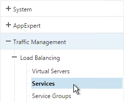
  1. On the left, expand Traffic Management, expand Load Balancing, and click Services.
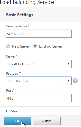
  2. On the right, click Add.
  3. Give the Service a descriptive name (e.g. svc-VSS01-SSL).
  4. Change the selection to Existing Server and select the Access Point, Security Server or internal (non-paired) Connection Server you created earlier.
  5. Change the Protocol to SSL_BRIDGE, and click OK.
  6. On the left, in the Monitors section, click where it says 1 Service to Load Balancing Monitor Binding.
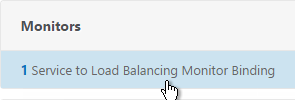
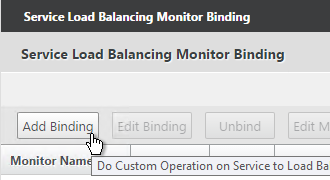
  7. Ignore the current monitor and click Add Binding.
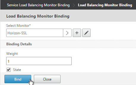
  8. Click the arrow next to Click to select.
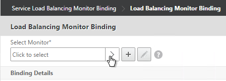
  9. Select the Horizon-SSL monitor and click Select.
  10. Then click Bind.
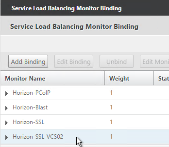
  11. If you are load balancing PCoIP through a View Security Server or Access Point, add monitors for PCoIP Secure Gateway (4172) and Blast Secure Gateway (8443) too. If 4172 or 8443 fails, then 443 needs to be marked DOWN.
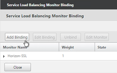
  12. If this is a Security Server, also add a monitor that has the IP address of the paired Connection Server. If the paired Connection Server is down, then the Security Server needs to marked as DOWN so NetScaler needs to stop sending connections to this Security Server.
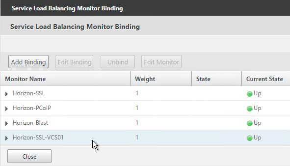
  13. The Last Response should indicate Success. If you bound multiple monitors to the Service, then the member will only be UP if all monitors succeed. There’s a refresh button on the top-right. Click Close when done.
  14. Then click Done.
  15. Right-click the first service and click Add.
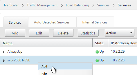
  16. Change the name to match the second Horizon Server or Access Point.
  17. Select Existing Server and use the Server drop-down to select to the second Horizon Server.
  18. The remaining configuration is identical to the first server. Click OK.
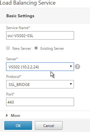
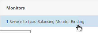
  19. You will need to configure the monitors again. They will be identical to the first server except for the monitoring of the paired View Connection Server. Click Done when done.
Other Ports Load Balancing Services

Here are general instructions for the remaining Horizon services. These instructions use Service Groups but you could just as easily add Services instead. See the above summaries for your specific configuration.

  1. On the left, go to Traffic Mgmt > Load Balancing > Service Groups.
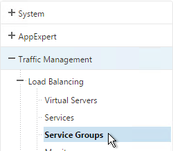
  2. On the right, click Add.
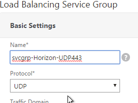
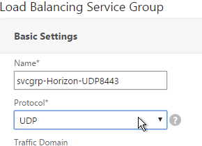
  3. Name it svcgrp-Horizon-UDP443 or similar. UDP 443 is for Blast Extreme in Horizon 7 through Access Points. If View Security Servers, the name should be svcgrp-Horizon-UDP8443.
  4. Change the Protocol to UDP. Click OK.
  5. Click where it says No Service Group Member.
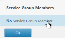
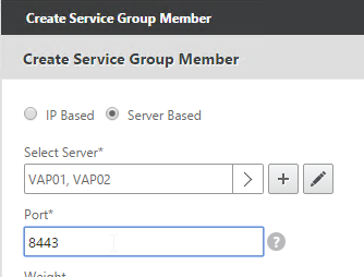
  6. Change the selection to Server Based and then click Click to select.
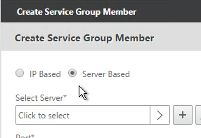
  7. Select your multiple Security Servers or multiple Access Points and click Select.
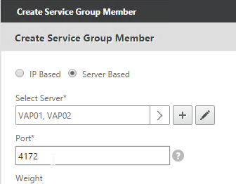
  8. If Access Points, enter 443 as the Port. If View Security Servers, enter 8443 as the port. Click Create.
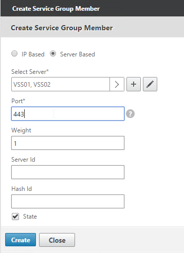
  9. Click OK.
  10. On the right, in the Advanced Settings column, add the Monitors section.
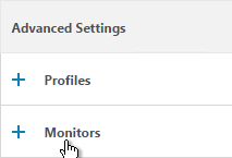
  11. Click where it says No Service Group to Monitor Binding.
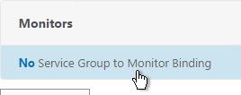
  12. Click to select.
  13. Select the Horizon-SSL monitor, click Select, and then click Bind.
  14. Click Done.
  15. Add another Service Group for PCoIP on TCP 4172.
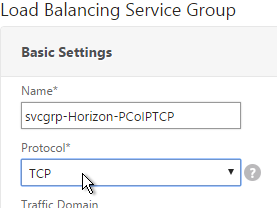
    1. Name = svcgrp-Horizon-PCoIPTCP or similar.
    2. Protocol = TCP

    3. Members = multiple Security Servers or multiple Access Points.
    4. Port = 4172.
    5. Monitors = Horizon-PCoIP. You can add the other monitors if desired.
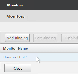
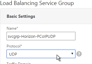
  16. Add another Service Group for PCoIP on UDP 4172.
    1. Name = svcgrp-Horizon-PCoIPUDP or similar.
    2. Protocol = UDP

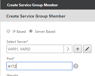
    3. Members = multiple Security Servers or multiple Access Points
    4. Port = 4172.
    5. Monitors = Horizon-PCoIP. You can add the other monitors if desired.
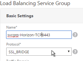
  17. Add another Service Group for SSL_BRIDGE 8443.
    1. Name = svcgrp-Horizon-TCP8443 or similar.
    2. Protocol = SSL_BRIDGE
    3. Members = multiple Security Servers or multiple Access Points
    4. Port = 8443.
    5. Monitors = Horizon-Blast. You can add the other monitors if desired.
  18. If you haven’t done this already, add another Service Group for UDP 8443 (Blast Extreme in Horizon 7).
    1. Name = svcgrp-Horizon-UDP8443 or similar.
    2. Protocol = UDP
    3. Members = multiple Security Servers or multiple Access Points
    4. Port = 8443.
    5. Monitors = Horizon-Blast. You can add the other monitors if desired.
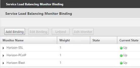
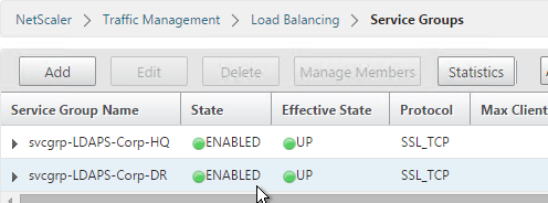
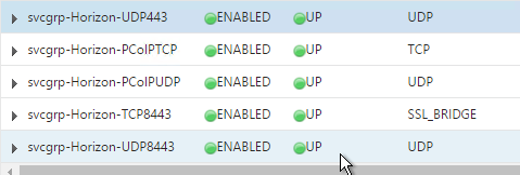
  19. The five service groups should look something like this:
Load Balancing Virtual Servers

Create separate load balancing vServers for internal and DMZ.

  • Internal VIP load balances the non-paired Internal Connections Servers. Access Point appliances also use this VIP to access the internal Connection Servers.
  • DMZ VIP load balances the Security Servers or Access Point appliances.

The paired View Connection Servers do not need to be load balanced.

For the internal Connection Servers you only need a load balancer for SSL_BRIDGE 443. If tunneling is disabled then you don’t need load balancers for the other ports (UDP/TCP 4172 and SSL_BRIDGE 8443).

However, Security Servers and Access Points listen on more ports so you will need separate load balancers for each port number. Here is a summary of their Virtual Servers, all listening on the same IP address. Depending on the configured protocol, you might not need all of these Virtual Servers.

  • Virtual Server on SSL_BRIDGE 443 – bind both Horizon SSL_BRIDGE 443 Services.
  • Virtual Server on UDP 443 (Horizon 7) – bind the UDP 443 service group.
  • Virtual Server on UDP 4172 – bind the PCoIPUDP service group.
  • Virtual Server on TCP 4172 – bind the PCoIPTCP service group.
  • Virtual Server on SSL_BRIDGE 8443 – bind the SSL_BRIDGE 8443 service group.
  • Virtual Server on UDP 8443 (Horizon 7) – bind the UDP 8443 service group.

Do the following to create the Virtual Servers:

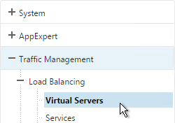
  1. On the left, under Traffic Management > Load Balancing, click Virtual Servers.
  2. On the right click Add.
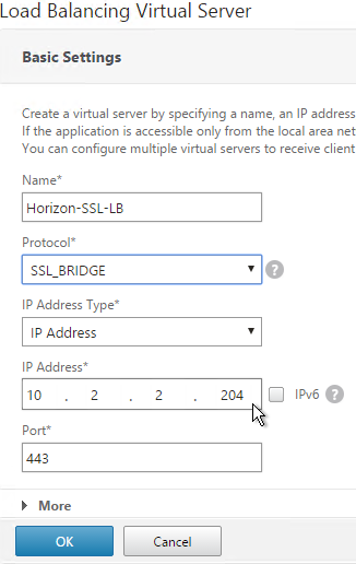
  3. Name it Horizon-SSL-LB or similar.
  4. Change the Protocol to SSL_BRIDGE.
  5. Specify a new VIP. This one VIP will be used for all of the Virtual Servers.
  6. Enter 443 as the Port.
  7. Click OK.
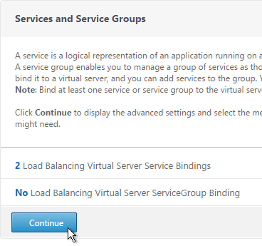
  8. On the left, in the Services and Service Groups section, click where it says No Load Balancing Virtual Server Service Binding.
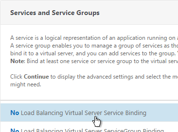
  9. Click the arrow next to Click to select.
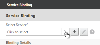
  10. Select the two View-SSL Services and click Select.
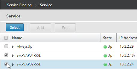
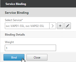
  11. Click Bind.
  12. Click Continue.
  13. Then click Done. Persistency will be configured later.
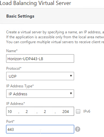
  14. If this is Horizon 7, and if this is an Access Point, then create another Load Balancing Virtual Server for UDP 443:
    1. Same VIP as the TCP 443 Load Balancer.
    2. Protocol = UDP, Port = 443
    3. Service Group Binding = the UDP 443 Service Group
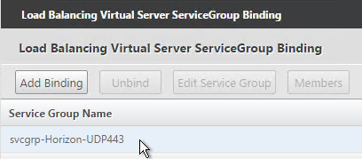
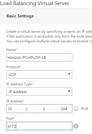
  15. If this is a Security Server or Access Point, then create another Load Balancing Virtual Server for PCoIP UDP 4172:
    1. Same VIP as the 443 Load Balancer.
    2. Protocol = UDP, Port = 4172
    3. Service Group Binding = the PCoIP UDP Service Group.
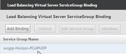
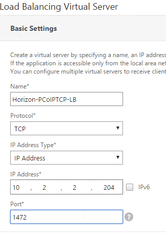
  16. If this is a Security Server or Access Point, then create another Load Balancing Virtual Server for PCoIP TCP 4172:
    1. Same VIP as the 443 Load Balancer.
    2. Protocol = TCP, Port = 4172
    3. Service Group Binding = the PCoIP TCP Service Group
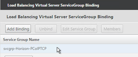
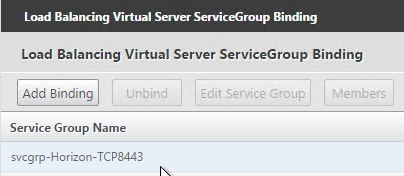
  17. If this is a Security Server or Access Point, then create another Load Balancing Virtual Server for SSL_BRIDGE 8443:
    1. Same VIP as the 443 Load Balancer.
    2. Protocol = SSL_BRIDGE, Port = 8443
    3. Service Group Binding = the TCP 8443 SSL_BRIDGE Service Group
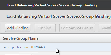
  18. If this is a Security Server or Access Point, then create another Load Balancing Virtual Server for UDP 8443:
    1. Same VIP as the 443 Load Balancer.
    2. Protocol = UDP, Port = 8443
    3. Service Group Binding = the UDP 8443 SSL_BRIDGE Service Group
  19. This gives you six Virtual Servers on the same VIP but different protocols and port numbers.

Persistency Group

For Security Servers and Access Points, users will first connect to SSL_BRIDGE 443 and be load balanced. Subsequent connections to the other port numbers must go to the same load balanced server. Create a Persistency Group to facilitate this.

For internal View Connection Servers, then you probably only have one SSL_BRIDGE load balancer for those servers, and thus you could configure persistence directly on that one load balancing vServer instead of creating a Persistency Group. However, since the Security Servers and Access Points have multiple load balancing vServers on different ports, then you need to bind them together into a Persistency Group.

  1. On the left, under Traffic Management, expand Load Balancing and click Persistency Groups.
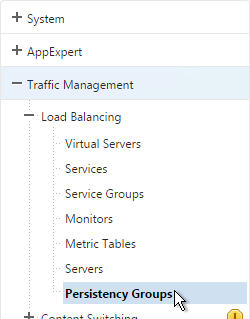
  2. On the right, click Add.
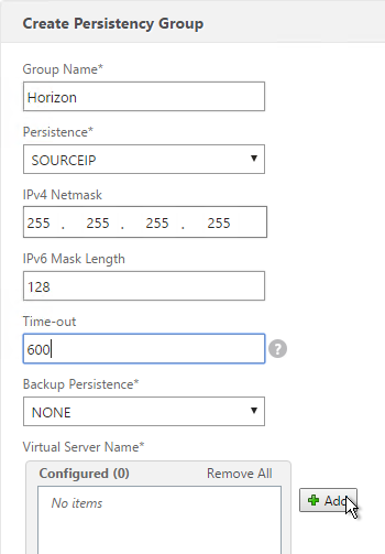
  3. Give the Persistency Group a name (e.g. Horizon).
  4. Change the Persistence to SOURCEIP.
  5. Enter a timeout that is equal to or greater than the timeout in Horizon View Administrator, which defaults to 10 hours (600 minutes).
  6. In the Virtual Server Name section, click Add.
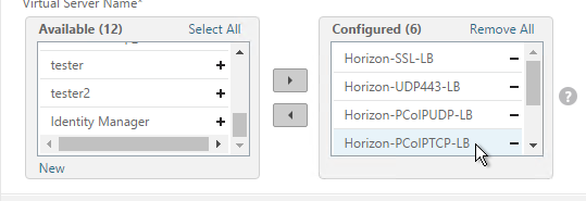
  7. Move all six Security Server / Access Point Load Balancing Virtual Servers to the right. Click Create.
CLI Commands

Here’s a list of CLI commands for the most basic configuration of two Access Points with Blast Extreme only (no PCoIP):

add server VAP01 10.2.2.187
add server VAP02 10.2.2.24
add lb monitor Horizon-SSL HTTP-ECV -send "GET /broker/xml" -recv clientlaunch-default -secure YES
add serviceGroup svcgrp-Horizon-SSL SSL_BRIDGE
add serviceGroup svcgrp-Horizon-UDP443 UDP
bind serviceGroup svcgrp-Horizon-SSL VAP01 443
bind serviceGroup svcgrp-Horizon-SSL VAP02 443
bind serviceGroup svcgrp-Horizon-SSL -monitorName Horizon-SSL
bind serviceGroup svcgrp-Horizon-UDP443 VAP01 443
bind serviceGroup svcgrp-Horizon-UDP443 VAP02 443
bind serviceGroup svcgrp-Horizon-UDP443 -monitorName Horizon-SSL
add lb vserver Horizon-SSL-LB SSL_BRIDGE 10.2.2.204 443
add lb vserver Horizon-UDP443-LB UDP 10.2.2.204 443
bind lb vserver Horizon-SSL-LB svcgrp-Horizon-SSL
bind lb vserver Horizon-UDP443-LB svcgrp-Horizon-UDP443
bind lb group Horizon Horizon-SSL-LB
bind lb group Horizon Horizon-UDP443-LB
set lb group Horizon -persistenceType SOURCEIP -timeout 600

Here’s a list of CLI commands for the more complicated Security Server configuration:

add server VSS01 10.2.2.187
add server VSS02 10.2.2.24
add lb monitor Horizon-PCoIP TCP -destPort 4172
add lb monitor Horizon-Blast TCP -destPort 8443
add lb monitor Horizon-SSL HTTP-ECV -send "GET /broker/xml" -recv clientlaunch-default -secure YES
add lb monitor Horizon-SSL-VCS01 HTTP-ECV -send "GET /broker/xml" -recv clientlaunch-default -destIP 10.2.2.19 -destPort 443 -secure YES
add lb monitor Horizon-SSL-VCS02 HTTP-ECV -send "GET /broker/xml" -recv clientlaunch-default -destIP 10.2.2.20 -destPort 443 -secure YES
add service svc-VSS01-SSL VSS01 SSL_BRIDGE 443
add service svc-VSS02-SSL VSS02 SSL_BRIDGE 443
bind service svc-VSS02-SSL -monitorName Horizon-SSL-VCS02
bind service svc-VSS02-SSL -monitorName Horizon-SSL
bind service svc-VSS02-SSL -monitorName Horizon-Blast
bind service svc-VSS02-SSL -monitorName Horizon-PCoIP
bind service svc-VSS01-SSL -monitorName Horizon-SSL-VCS01
bind service svc-VSS01-SSL -monitorName Horizon-Blast
bind service svc-VSS01-SSL -monitorName Horizon-PCoIP
bind service svc-VSS01-SSL -monitorName Horizon-SSL
add serviceGroup svcgrp-Horizon-UDP443 UDP
add serviceGroup svcgrp-Horizon-PCoIPTCP TCP
add serviceGroup svcgrp-Horizon-PCoIPUDP UDP
add serviceGroup svcgrp-Horizon-TCP8443 SSL_BRIDGE
add serviceGroup svcgrp-Horizon-UDP8443 UDP
bind serviceGroup svcgrp-Horizon-UDP443 VSS01 443
bind serviceGroup svcgrp-Horizon-UDP443 VSS02 443
bind serviceGroup svcgrp-Horizon-UDP443 -monitorName Horizon-SSL
bind serviceGroup svcgrp-Horizon-PCoIPTCP VSS01 4172
bind serviceGroup svcgrp-Horizon-PCoIPTCP VSS02 4172
bind serviceGroup svcgrp-Horizon-PCoIPTCP -monitorName Horizon-PCoIP
bind serviceGroup svcgrp-Horizon-PCoIPUDP VSS01 4172
bind serviceGroup svcgrp-Horizon-PCoIPUDP VSS02 4172
bind serviceGroup svcgrp-Horizon-PCoIPUDP -monitorName Horizon-PCoIP
bind serviceGroup svcgrp-Horizon-TCP8443 VSS01 8443
bind serviceGroup svcgrp-Horizon-TCP8443 VSS02 8443
bind serviceGroup svcgrp-Horizon-TCP8443 -monitorName Horizon-Blast
bind serviceGroup svcgrp-Horizon-UDP8443 VSS01 8443
bind serviceGroup svcgrp-Horizon-UDP8443 VSS02 8443
bind serviceGroup svcgrp-Horizon-UDP8443 -monitorName Horizon-Blast
add lb vserver Horizon-SSL-LB SSL_BRIDGE 10.2.2.204 443
add lb vserver Horizon-UDP443-LB UDP 10.2.2.204 443
add lb vserver Horizon-PCoIPUDP-LB UDP 10.2.2.204 4172
add lb vserver Horizon-PCoIPTCP-LB TCP 10.2.2.204 4172
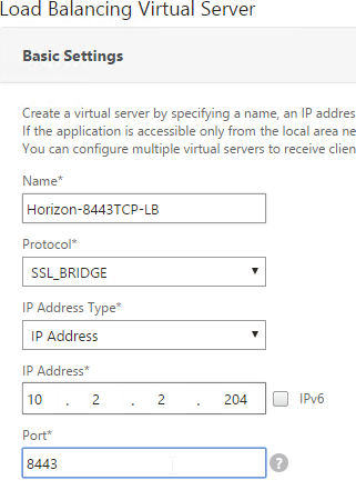
add lb vserver Horizon-8443TCP-LB SSL_BRIDGE 10.2.2.204 8443
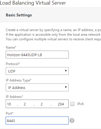
add lb vserver Horizon-8443UDP-LB UDP 10.2.2.204 8443
bind lb vserver Horizon-SSL-LB svc-VSS01-SSL
bind lb vserver Horizon-SSL-LB svc-VSS02-SSL
bind lb vserver Horizon-UDP443-LB svcgrp-Horizon-UDP443
bind lb vserver Horizon-PCoIPTCP-LB svcgrp-Horizon-PCoIPTCP
bind lb vserver Horizon-PCoIPUDP-LB svcgrp-Horizon-PCoIPUDP
bind lb vserver Horizon-8443TCP-LB svcgrp-Horizon-TCP8443
bind lb vserver Horizon-8443UDP-LB svcgrp-Horizon-UDP8443
bind lb group Horizon Horizon-SSL-LB
bind lb group Horizon Horizon-UDP443-LB
bind lb group Horizon Horizon-PCoIPUDP-LB
bind lb group Horizon Horizon-PCoIPTCP-LB
bind lb group Horizon Horizon-8443TCP-LB
bind lb group Horizon Horizon-8443UDP-LB
set lb group Horizon -persistenceType SOURCEIP -timeout 600

Horizon View Configuration – Security Servers

This section is not needed for Access Points. For Access Points, the secure gateways should be disabled, not enabled.

  1. On the Security Servers (or Connection Servers), request a certificate that matches the FQDN that resolves to the Load Balancing VIP.
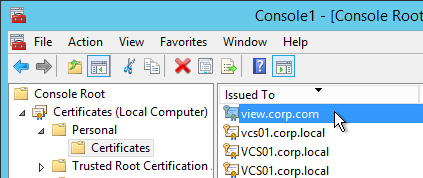
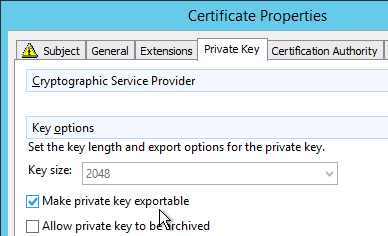
  2. Make sure the private key is exportable.
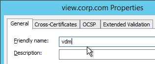
  3. Set the Friendly Name to vdm and restart the View Security Server services.
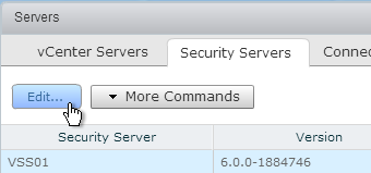
  4. In View Administrator, go to View Configuration > Servers.
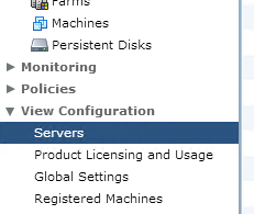
  5. On the right, switch to the Security Servers tab.
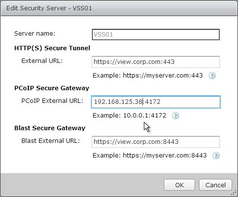
  6. Highlight a server and click Edit.
  7. Change the URLs to the FQDN that resolves to the load balancing VIP.
  8. Change the PCoIP URL to the VIP. For View Security Servers, this is typically a public IP that is NAT’d to the DMZ Load Balancing VIP.
SSL Virtual Servers – NetScaler 11

Last Modified: Nov 6, 2020 @ 7:10 am

This page contains generic instructions for all SSL Virtual Servers including: Load Balancing, NetScaler Gateway, and Content Switching.

Navigation

💡 = Recently Updated

Cipher Group

References:

  1. Ryan Butler has a PowerShell script at Github that can automate NetScaler SSL configuration to get an A+.  💡
  2. The easiest way to create a cipher group is from the CLI. See Citrix Blogs Scoring an A+ at SSLlabs.com with Citrix NetScaler – 2016 update for cipher group CLI commands.
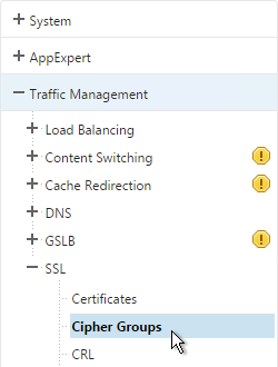
  3. Go to Traffic Management > SSL > Cipher Groups.
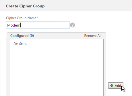
  4. On the right, click Add.
  5. Name it Modern or similar.
  6. In the middle, click Add.
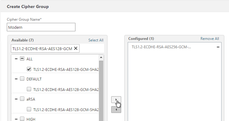
  7. Use the search box to find a particular cipher.
  8. Check the box next to one of the results and click the arrow to move it to the right. See Citrix Blogs Scoring an A+ at SSLlabs.com with Citrix NetScaler – 2016 update for recommended ciphers. The recommended ciphers vary based on the hardware platform and support for older clients.
  9. Click Create when done.

Default SSL Profile

In NetScaler 11.0 build 64 and newer, SSL Profiles are much more functional. You can use SSL Profiles to disable SSLv3, bind ciphers, and bind ECC curves.

Note: the default SSL Profile affects all SSL Virtual Servers unless you create additional SSL Profiles and bind the additional SSL Profiles to individual SSL Virtual Servers.

Citrix CTX201710 Cipher/Protocol Support Matrix of NetScaler Appliances – VPX 11.0 build 64 and older supports fewer ciphers than MPX. This was corrected in 11.0 build 65.

NetScaler 11.0 build 65 adds TLS 1.2 for back-end connections from VPX appliances. However, it does not appear to be possible to enable TLS 1.2 on SSL Profiles on VPX. If you don’t enable the default SSL profiles then you can enable TLS 1.2 on each Service Group or Service. If you are using VPX, don’t enable Default SSL profile as detailed in this section. 💡

NetScaler 11.0 build 64 and older does not do a proper handshake with TLS 1.2 IIS servers. To work around this problem, disable TLS 1.2 on the load balancing services as detailed at CTX205578 Back-End Connection on TLS 1.1/1.2 from NetScaler to IIS Servers Break. Or upgrade to 11.0 build 65.

Also see CTX205576 NetScaler to Back-End SSL Handshake Failure on Disabling SSL 3.0 on Back-End (Physical) Servers. These articles describe both SSL services and SSL_BRIDGE services.

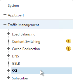
  1. Go to Traffic Management > SSL.
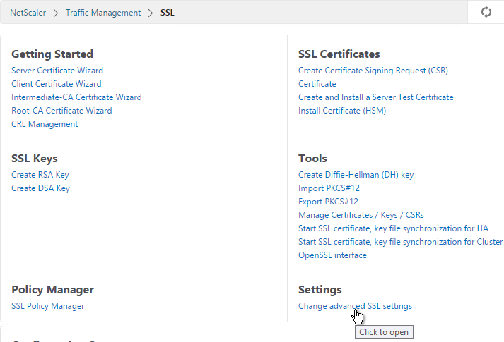
  2. On the right, in the right column, click Change advanced SSL settings.
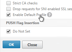
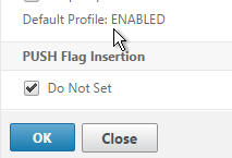
  3. Near the bottom, check the box next to Enable Default Profile. Note: this will change SSL settings on all SSL Virtual Servers to match the default SSL profile. You might want to do this during a maintenance window. Click OK when done.
  4. If you go back into Advanced SSL Settings, notice that the Default Profile is enabled and there’s no way to disable it.
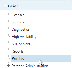
  5. To change the default SSL profile, on the left, go to System > Profiles.
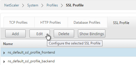
  6. On the right, switch to the SSL Profile tab.
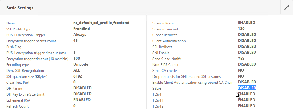
  7. Highlight the frontend or backend default profile and click Edit. Note: this is the same place where you can create more SSL profiles.
  8. Notice that SSLv3 is disabled by default.
  9. If you do any SSL Offload (SSL on the client side, HTTP on the server side) then you’ll need to edit the Basic Settings section and enable SSL Redirect. Or you can create a new SSL Profile with this option enabled. It’s near the bottom of the section. With this option enabled, any 301/302 redirects from the server with HTTP locations are rewritten to HTTPS locations. You might need this option for StoreFront load balancing if doing SSL Offload.
  10. It’s currently not possible to bind user-defined cipher groups using the GUI but you can easily do this using the CLI. First unbind the DEFAULT cipher group and then bind the Modern cipher group.
    unbind ssl profile ns_default_ssl_profile_frontend -cipherName DEFAULT
    bind ssl profile ns_default_ssl_profile_frontend -cipherName Modern
    

  11. If you edit one of your SSL Virtual Servers, there’s an SSL Profile section indicating that the default profile is being used. You can change the binding to a different SSL Profile.

Bind Certificate, Bind Cipher Group, Disable SSLv3, Enable STS

NetScaler 11.0 build 64 and older do not do a proper handshake with TLS 1.2 IIS servers. To work around this problem, disable TLS 1.2 on the load balancing services as detailed at CTX205578 Back-End Connection on TLS 1.1/1.2 from NetScaler to IIS Servers Break. Also see CTX205576 NetScaler to Back-End SSL Handshake Failure on Disabling SSL 3.0 on Back-End (Physical) Servers. These articles describe both SSL services and SSL_BRIDGE services.

  1. When creating the SSL Virtual Server, on the left, in the Certificates section, click where it says No Server Certificate.
  2. Click where it says Click to select.
  3. Select a certificate and click Select.
  4. Click Bind.

    bind ssl vserver MyvServer -certkeyName MyCert
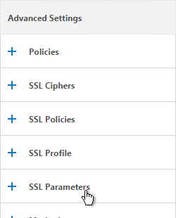
  5. If the SSL Parameters section isn’t added, on the right, in the Advanced Settings column, click SSL Parameters.
  6. On the left, in the SSL Parameters section, click the pencil icon.
  7. Uncheck the box next to SSLv3. This removes a security vulnerability. Make sure TLSv11 and TLSv12 are enabled. Click OK.

    set ssl vserver MyvServer -ssl3 DISABLED -tls11 ENABLED -tls12 ENABLED
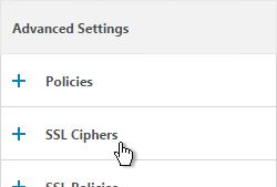
  8. On the right, in the Advanced Settings column, click SSL Ciphers.
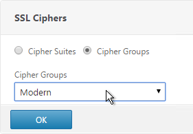
  9. On the left, in the SSL Ciphers section, select the previously created Modern Cipher Group and click OK.

    unbind ssl vserver MyvServer -cipherName ALL
    bind ssl vserver MyvServer -cipherName Modern
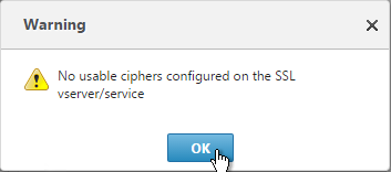
  10. If you see a warning about No usable ciphers, click OK and ignore it.
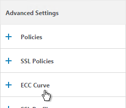
  11. SSL Virtual Servers created on newer versions of NetScaler will automatically have ECC Curves bound to them. However, if this appliance was upgraded from an older version then the ECC Curves might not be bound. On the right, in the Advanced Settings section, click ECC Curve.
  12. On the left, in the ECC Curve section, click where it says No ECC Curve.
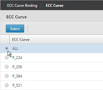
  13. Click to select.
  14. Choose ALL and click Select.

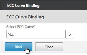
    bind ssl vserver MyvServer -eccCurveName ALL
  15. Click Bind.
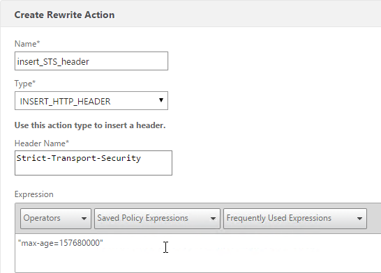
  16. Consider enabling Strict Transport Security by creating a rewrite policy and binding it to this SSL Virtual Server. See Anton van Pelt Make your NetScaler SSL VIPs more secure (Updated). Also see CTX205221 How Do I Do HSTS on NetScaler?

    enable ns feature rewrite
    
    add rewrite action insert_STS_header insert_http_header Strict-Transport-Security "\"max-age=157680000\""
    
    add rewrite policy insert_STS_header true insert_STS_header
    
    bind lb vserver MyvServer -policyName insert_STS_header -priority 100 -gotoPriorityExpression END -type RESPONSE

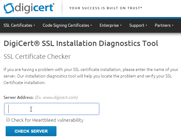
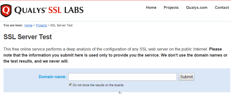
SSL Tests

After you’ve created an SSL Virtual Server, run the following tests:

SSL Redirect – Down vServer Method

If you created an SSL Virtual Server that only listens on SSL 443, then users must enter https:// when navigating to the website. To make it easier for the users, create another load balancing Virtual Server on the same VIP but listens on HTTP 80 and then redirects the user’s browser to reconnect on SSL 443.

The Down Virtual Server Method is easy but the Redirect Virtual Server must be down in order for the redirect to take effect. Another option is to use Responder policies to perform the redirect.

  1. On the left, under Traffic Management > Load Balancing, click Virtual Servers.

  2. On the right, find the SSL Virtual Server you’ve already created, right-click it and click Add. Doing it this way copies some of the data from the already created Virtual Server.
  3. Change the name to indicate that this new Virtual Server is an SSL Redirect.
  4. Change the Protocol to HTTP on Port 80.
  5. The IP Address should already be filled in. It must match the original SSL Virtual Server. Click OK.
  6. Don’t select any services. This vServer must intentionally be marked down so the redirect will take effect. Click Continue.
  7. On the right, in the Advanced Settings column, click Protection.
  8. In the Redirect URL field, enter the full URL including https://. For example: https://storefront.company.com/Citrix/StoreWeb. Click OK.

  9. Click Done.
  10. When you view the SSL redirect Virtual Server in the list, it will have a state of DOWN. That’s OK. The Port 80 Virtual Server must be DOWN for the redirect to work.

SSL Redirect – Responder Method

The Down Virtual Server Method is easy but the Redirect Virtual Server must be down in order for the redirect to take effect. Another option is to use Responder policies to perform the redirect. This method requires the Redirect Virtual Server to be UP.

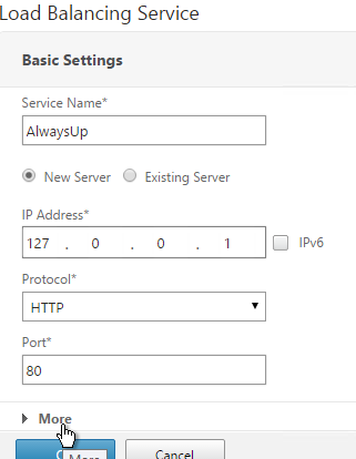
  1. Create a dummy Load Balancing service. This dummy service can be bound to multiple Redirect Virtual Servers.

  2. Name it AlwaysUp or similar.
  3. Use a loopback IP address (e.g. 127.0.0.1). After the service is created it changes to a NetScaler-owned IP.
  4. Click the More link.
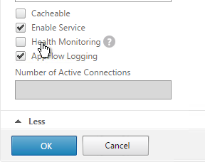
  5. This dummy service must always be UP so uncheck the box next to Health Monitoring. Click OK and then click Done.

    add server 127.0.0.1 127.0.0.1
    add service AlwaysUp 127.0.0.1 HTTP 80 -healthMonitor NO
  6. On the left, expand AppExpert and click Responder.
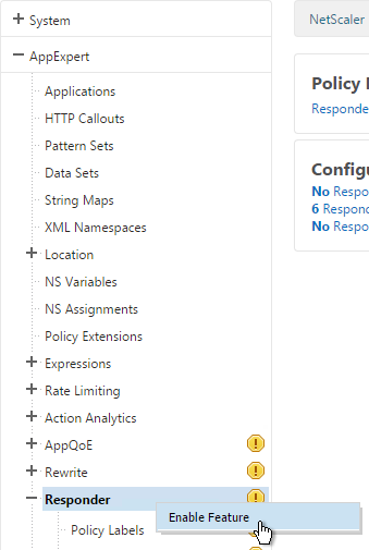
  7. If Responder is not enabled, right-click Responder and click Enable Feature.

    enable ns feature RESPONDER
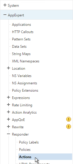
  8. Under Responder, click Actions.
  9. On the right, click Add.
  10. Give the action a name.
  11. Change the Type to Redirect.
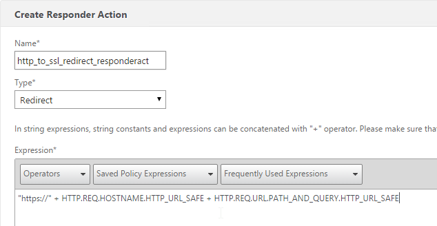
  12. Enter an expression. The following expression can be used by multiple Redirect Virtual Servers. Or you can create a Responder Action with a more specific Target. Click Create.
    "https://" + HTTP.REQ.HOSTNAME.HTTP_URL_SAFE + HTTP.REQ.URL.PATH_AND_QUERY.HTTP_URL_SAFE

    add responder action http_to_ssl_redirect_responderact redirect "\"https://\" + HTTP.REQ.HOSTNAME.HTTP_URL_SAFE + HTTP.REQ.URL.PATH_AND_QUERY.HTTP_URL_SAFE" -responseStatusCode 302
  13. On the left, under Responder, click Policies.
  14. On the right, click Add.
  15. Give the policy a name.
  16. Select the previously created Responder action.
  17. For the expression, enter the following. Then click Create.
    HTTP.REQ.IS_VALID

    add responder policy http_to_ssl_redirect_responderpol HTTP.REQ.IS_VALID http_to_ssl_redirect_responderact
  18. Create a Load Balancing Virtual Server with Protocol HTTP and Port 80. The VIP should match an existing SSL Virtual Server or NetScaler Gateway Virtual Server.

  19. Bind the Dummy (AlwaysUp) service, and click OK.

  20. On the right, in the Advanced Settings column, click Policies.
  21. Click the plus icon in the top right of the Policies box.
  22. Select Responder and click Continue.
  23. Select the Redirect Responder policy and click Bind. Then click Done.

    add lb vserver MyvServer-HTTP-SSLRedirect HTTP 10.2.2.201 80
    
    bind lb vserver storefront.corp.com-HTTP-SSLRedirect AlwaysUp
    
    bind lb vserver storefront.corp.com-HTTP-SSLRedirect -policyName http_to_ssl_redirect_responderpol -priority 100 -gotoPriorityExpression END -type REQUEST
  24. The primary advantage of this method is that the Redirect Virtual Server is UP.

Domain Controller (LDAPS) Load Balancing – NetScaler 11

Last Modified: Nov 7, 2020 @ 6:35 am

Navigation

Overview

If you plan to use LDAP (Active Directory) for NetScaler Gateway or NetScaler management authentication, load balance the Domain Controllers that are used for authentication.

An alternative to load balancing is to configure NetScaler Gateway and NetScaler management authentication with multiple authentication policies, each pointing to a single Domain Controller. However, NetScaler will try each authentication policy until it finds one that works. If the user enters a wrong password and if you have three authentication policies pointing to different Domain Controllers in the same domain then three different failure attempts will be recorded thus causing premature account lockout. Use Load Balancing to avoid this behavior.

This page details LDAPS, aka Secure LDAP. This protocol requires certificates to be installed on the Domain Controllers. When a user’s password expires, Active Directory does not allow password changes over clear text LDAP so LDAPS must be used instead. Make sure you have certificates installed on your Domain Controllers. The easiest way to accomplish that is to deploy a Microsoft Certificate Authority. Once that’s done the Domain Controllers will request certificates automatically.

An ldaps monitor can be used to verify that the Domain Controller is functional. The ldaps monitor will login as an account, perform an LDAP query, and look for a successful response. The ldaps monitor uses a service account to login. Make sure the service account’s password does not expire. Domain User permissions are sufficient. Since this monitor is a Perl script, it uses NSIP as the source IP.

If you have Domain Controllers in multiple datacenters, you can create multiple load balancing Virtual Servers and cascade them so that the local Domain Controllers are used first, and if they’re not available, then the Virtual Server fails over to Domain Controllers in remote datacenters.

The Load Balancing Virtual Server for LDAPS can be TCP or SSL_TCP:

  • If the protocol is TCP, then SSL-encrypted LDAP traffic is not terminated on the NetScaler, and is simply forwarded to the LDAP servers. If your LDAP client needs to verify the LDAP server certificate, then this Load Balancing configuration will not work, since each back-end LDAP server will have a different certificate.
  • If your Load Balancing Virtual Server is protocol SSL_TCP, then a certificate must be installed on the NetScaler and bound to the Load Balancing Virtual Server. SSL is terminated at the NetScaler and re-encrypted before sending it to the destination Domain Controller. The primary benefit of NetScaler SSL termination is that your LDAP clients can verify the Virtual Server SSL certificate.

When NetScaler uses a local (same appliance) load balanced Virtual Server for LDAPS authentication, the traffic is sourced from the NetScaler SNIP (Subnet IP). When NetScaler uses a direct connection to a Domain Controller without going through a local Load Balancing Virtual Server, or if NetScaler uses a remote (different appliance) Load Balancing VIP, then the traffic is sourced from the NetScaler NSIP (NetScaler IP). Adjust firewall rules accordingly.

LDAPS Monitor

Note: Perl monitor uses NSIP as the source IP.

  1. In the NetScaler Configuration Utility, expand Traffic Management, expand Load Balancing, and click Monitors.
  2. On the right, click Add.
  3. Name the monitor ldaps-Corp or similar. The ldaps monitor logs into Active Directory, performs an LDAP query, and looks for a successful response. The monitor configuration has domain specific information, so if you have multiple Active Directory domains, then you will need multiple ldaps monitors. Include the domain name in the monitor name.
  4. Change the Type to LDAP.
  5. Scroll down and check the box next to Secure.
  6. Scroll back up and switch to the Special Parameters tab.
  7. On the Special Parameters tab, use the Script Name drop-down list to select the nsldap.pl file.
  8. In the Base DN field, enter your domain name in LDAP format (e.g. dc=company,dc=com)
  9. In the Bind DN field, enter the UPN login (e.g. ctxsvc@company.com) of a service account in the domain that can browse all objects. Any normal Domain User should be sufficient. Just make sure the password doesn’t expire.
  10. In the Filter field, enter cn=builtin. This limits the search results.
  11. In the Password field, enter the password for the service account. Make sure there is no semicolon in the password or the script will be unable to parse the parameters.
  12. Click Create.

    add lb monitor LDAP-Corp LDAP -scriptName nsldap.pl -dispatcherIP 127.0.0.1 -dispatcherPort 3013 -password Passw0rd -secure YES -baseDN "dc=corp,dc=local" -bindDN "corp\\ctxsvc" -filter cn=builtin
  13. If you have multiple domains, then create additional monitors: one for each domain.

Servers

  1. On the left, expand Traffic Management, expand Load Balancing, and click Servers.
  2. On the right, click Add.
  3. Enter a descriptive server name, usually it matches the actual server name.
  4. Enter the IP address of the server.
  5. Enter comments to describe the server. Click Create.

    add server AD01 10.2.2.11
    add server AD01 10.2.2.12
  6. Continue adding Domain Controllers.

Service Groups

  1. On the left, expand Traffic Management, expand Load Balancing, and click Service Groups.
  2. On the right, click Add
    .
  3. You will create one Service Group per datacenter. Enter a name reflecting the name of the data center. Also, you will create a set of service groups per Active Directory domain so include the domain name.
  4. Change the Protocol to SSL_TCP. Scroll down, and click Continue.
  5. On the left, in the Service Group Members section, click where it says No Service Group Member.
  6. If you did not create server objects then enter the IP address of a Domain Controller in this datacenter. If you previously created a server object then change the selection to Server Based, and select the server object. In the Port field, enter 636 (LDAPS).
  7. Note: Any Domain Controller you add to this list must have an SSL certificate installed. The easiest way to install SSL certificates on the Domain Controllers is with Active Directory Certificate Services since it installs the certificates automatically.

  8. To add more members, click where it says 1 Service Group Member, and then click Add. Click Close when done.

  9. On the right, in the Advanced Settings column, click Monitors.
  10. On the left, in the Monitors section, click where it says No Service Group to Monitor Binding.
  11. Click the arrow next to Click to select.
  12. Select your new LDAPS monitor and click Select.
  13. Click Bind.
  14. To verify the member is up, click in the Service Group Members section.
  15. Highlight a member, and click Monitor Details.
  16. It should say Probe successful. Click OK.
  17. If the monitor doesn’t work, use ldp.exe to verify the Domain Controller certificate.
  18. Click Done to finish creating the Service Group.

    add serviceGroup svcgrp-LDAP-Corp SSL_TCP
    bind serviceGroup svcgrp-LDAP-Corp AD01 636
    bind serviceGroup svcgrp-LDAP-Corp AD02 636
    bind serviceGroup svcgrp-LDAP-Corp -monitorName LDAP-Corp
  19. The Service Group is displayed as UP. If not, click the refresh icon on the top right.
  20. Add additional service groups for Domain Controllers in each data center.

Virtual Server

  1. Create or import a certificate that matches the FQDN that resolves to the new Load Balancing VIP for LDAPS.
  2. On the left, expand Traffic Management, expand Load Balancing, and click Virtual Servers.

  3. On the right, click Add.
  4. Name it lbvip-LDAPS-Corp-HQ or similar. You will create one Virtual Server per datacenter so include the datacenter name. Also, each domain has a separate set of Virtual Servers so include the domain name.
  5. Change the Protocol drop-down to SSL_TCP.
  6. Enter a Virtual IP. This VIP cannot conflict with any other IP/Port already being used. You can use an existing VIP that is not already listening on TCP 636.
  7. Enter 636 as the Port. Click OK.
  8. On the left, in the Service Group section, click where it says No Load Balancing Virtual Server ServiceGroup Binding.
  9. Click the arrow next to Click to select.
  10. Select the previously created Service Group, and click Select.
  11. Click Bind.
  12. Click Continue.
  13. On the left, in the Certificates section, click where it says No Server Certificate.
  14. Click the arrow next to Click to select.
  15. Select a certificate that matches the FQDN that will resolve to this VIP. Click Select.
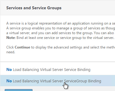
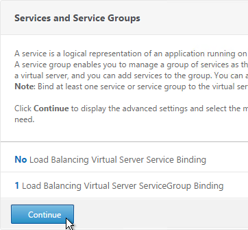
  16. Click Bind.
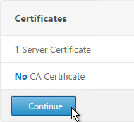
  17. Click Continue.

    add lb vserver lbvip-LDAP-Corp SSL_TCP 10.2.2.210 636 -persistenceType NONE -cltTimeout 9000
    
    bind lb vserver lbvip-LDAP-Corp svcgrp-LDAP-Corp
  18. If you haven’t enabled the Default SSL Profile, then perform other normal SSL configuration including: disable SSLv3, and bind a Modern Cipher Group.
    bind ssl vserver MyvServer -certkeyName MyCert
    
    set ssl vserver MyvServer -ssl3 DISABLED -tls11 ENABLED -tls12 ENABLED
    
    unbind ssl vserver MyvServer -cipherName ALL
    
    bind ssl vserver MyvServer -cipherName Modern
    
    bind ssl vserver MyvServer -eccCurveName ALL
  19. Click Done to finish creating the Virtual Server.
  20. The new Virtual Server should show as Up.
  21. Create additional Virtual Servers for each datacenter. These additional Virtual Servers do not need a VIP so change the IP Address Type to Non Addressable. Only the first Virtual Server will be accessible.

    add lb vserver lbvip-LDAP-Corp-Backup SSL_TCP 0.0.0.0 0
  22. Notice that the additional datacenter Virtual Servers show up with an IP Address of 0.0.0.0 and port of 0.
  23. After you are done creating a Virtual Server for each datacenter, right-click the primary datacenter’s Virtual Server, and click Edit.
  24. On the right, in the Advanced Settings column, click Protection.
  25. On the left, in the Protection section, change the Backup Virtual Server to one of the other datacenter Virtual Servers. If all of the services in this datacenter are DOWN, the backup Virtual Server will be used instead. You can cascade multiple Virtual Servers using this method. Click OK and Done.

    set lb vserver lbvip-LDAP-Corp -backupVServer lbvip-LDAP-Corp-Backup

Clear Text LDAP

Citrix Command Center does not support Secure LDAP so you will need to do the following:

  1. Create a regular LDAP monitor that does not have the secure box checked.
  2. Create Service Groups of Protocol TCP and Port 389.
  3. Create a Load Balancing Virtual Server of Protocol TCP on port 389. Bind the Service Groups to it.

Next Steps

You may now use this Virtual IP in your LDAP authentication policies for NetScaler Gateway or NetScaler management login.