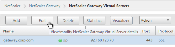
Navigation
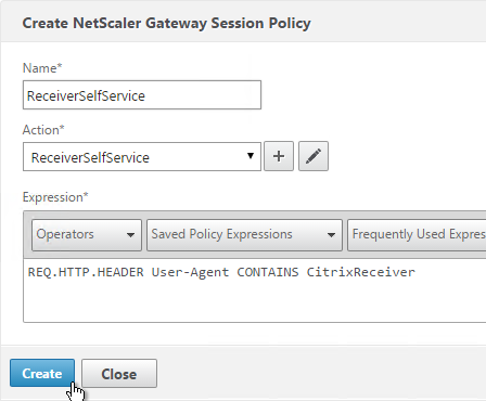
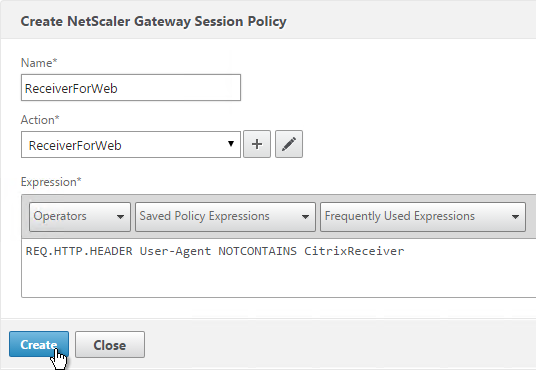
Use this procedure to load balance Horizon View Connection Servers, Horizon View Security Servers, and/or VMware Access Points.
- Overview
- Load Balancing Monitors
- Load Balancing Servers
- Load Balancing Services
- Load Balancing Virtual Servers
- Persistency Group
- CLI Commands
- Horizon Configuration
Overview
Servers/Appliances
There are two VMware-provided remote access solutions for Horizon:
Access Points are preferred over Security Servers for the following reasons:
- No need to pair with internal Connection Servers. This simplifies the configuration.
- Linux appliance instead of Windows server.
- Authentication can be offloaded to Access Point. This includes: Smart Cards, RSA, and RADIUS.
If you are using Access Points instead of Security Servers then you’ll have the following machines in a highly available Horizon infrastructure:
- Two Internal Connection Servers – these need to be load balanced on an internal VIP. Internal users connect to the internal VIP.
- Two DMZ Access Point appliances – these need to be load balanced on a DMZ VIP. External users connect to the DMZ VIP. Access Points connect to the internal VIP.
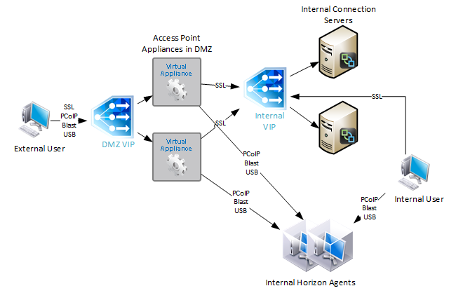
With Security Servers instead of Access Points, a typical Horizon Infrastructure will have at least six connection servers:
- Two Internal Connection Servers – these need to be load balanced on an internal VIP. Internal users connect to the internal VIP.
- Two DMZ Security Servers – these need to be load balanced on a DMZ VIP. External users connect to the DMZ VIP. Each Security Servers connects directly to a “paired” Connection Servers.
- The DMZ Security Servers are paired with two additional internal “paired” Connection Servers. There is no need to load balance the internal Paired Connection Servers. However, we do need to monitor them.

Since Security Servers are paired with Connection Servers, you need to configure load balancing monitors to disable the Security Server if the paired Connection Server is not accessible. Since Access Points are not paired with Connection Servers, you don’t need this special monitoring configuration.
Protocols/Ports
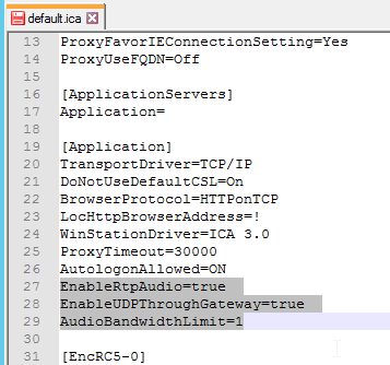
Horizon 7 introduces a new Blast Extreme protocol. VMware Technical White Paper Blast Extreme Display Protocol in Horizon 7.
For VMware Access Point, Blast Extreme only needs TCP and UDP 443 only. HTML Access in Horizon 7 also uses Blast Extreme protocol (TCP/UDP 443). If you use VMware Access Point with Blast Extreme exclusively, then the number of ports is minimal, and load balancing configuration is simplified. Here are typical load balancing port requirements for Access Point with Blast Extreme only:
- TCP 443
- UDP 443
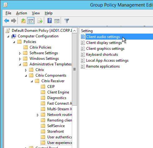
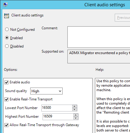
Note: UDP is disabled by default, but it can be enabled using a Blast GPO setting.
For View Security Servers, and Blast Extreme protocol only, then the following load balancing ports are needed. Note: Access Point supports 443 port sharing, but Security Servers do not.
- TCP 443
- TCP 8443
- UDP 8443
Note: UDP is disabled by default, but it can be enabled using a Blast GPO setting.
For all other configurations that don’t use Blast Extreme (PCoIP, HTML Blast), the following ports must be load balanced:
- TCP 443
- TCP 4172
- UDP 4172
- TCP 8443
If you are load balancing internal Connection Servers only, and if the Secure Gateways are disabled, then the only port you need to load balance is:
- TCP 443
VMware requires server persistence to apply across multiple load balanced port numbers. If a user is load balanced to a particular View Connection Server on TCP 443, then the connection on UDP 4172 must go the same View Connection Server. Normally load balancing persistence only applies to a single port number, so whatever sever was selected on 443 won’t be considered for the 4172 connection. But in NetScaler, you can configure a Persistency Group to use a single persistency across multiple load balancing vServers (different port numbers). In F5, you configure Match Across.
Also see Load Balancing with Access Point by Mark Benson at VMware Communities 💡
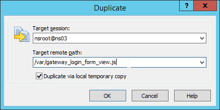
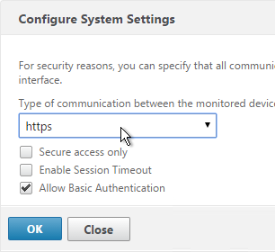
This topic primarily focuses on NetScaler GUI configuration. Alternatively, you can skip directly to the CLI commands.
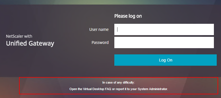
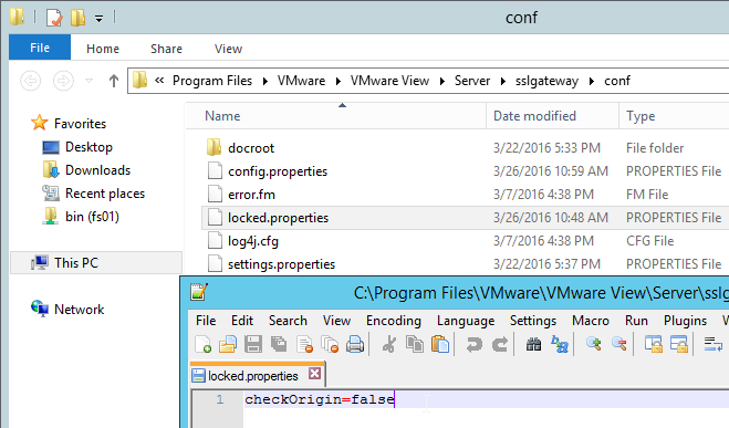
Horizon 7 Origin Check
Horizon 7 might not accept your load balanced DNS name unless it’s the same name configured in the Connection Server’s Secure Tunnel configuration. You can change this behavior by disabling Origin Check as detailed at VMware 2144768 Accessing the Horizon View Administrator page displays a blank error window in Horizon 7. Note: this configuration is almost mandatory for Access Points since Secure Tunnel is disabled on the Connection Servers.
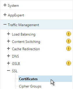
Load Balancing Monitors
Users connect to Connection Servers, Security Servers, and Access Point appliances on multiple ports: TCP 443, UDP 443, TCP 8443, UDP 8443, TCP 4172, and UDP 4172. Users will initially connect to TCP port 443 and then be redirected to one of the other ports on the same server/appliance initially used for the TCP 443 connection. If TCP 443 is up but UDP 4172 is down on the same server/appliance then you probably wan’t to take TCP 443 down too. To facilitate this, create a monitor for each of the ports and bind all of the monitors to the TCP 443 service. Then if any of the monitors goes down then TCP 443 is also take down.
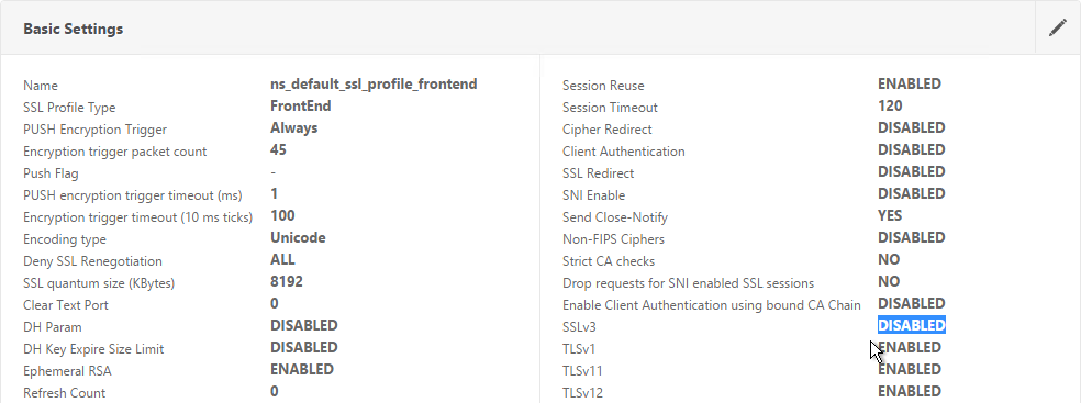
Note: TLS 1.0 is disabled in Horizon View 6.2.1 and newer. If your NetScaler supports TLS 1.2 on the back end then this isn’t a problem. Back-end TLS 1.2 was added to NetScaler MPX/SDX in 10.5 build 58. And it was added to NetScaler VPX in 11.0 build 65. For older NetScaler builds, you’ll need to enable TLS 1.0 (and HTML Blast) in Horizon or else the monitors won’t work.
In NetScaler VPX 11.0 build 64, secure HTTP monitors attached to SSL_BRIDGE services try to use TLS 1.2 instead of TLS 1.0. To fix this problem, run set ssl parameter -svctls1112disable enable -montls1112disable enable as detailed at CTX205578 Back-End Connection on TLS 1.1/1.2 from NetScaler to IIS Servers Break.
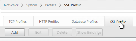
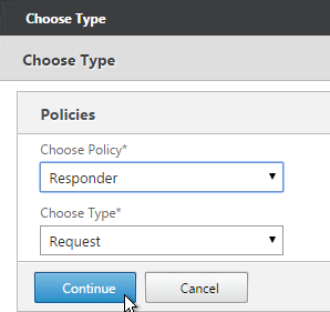
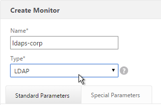
SSL Monitor
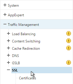
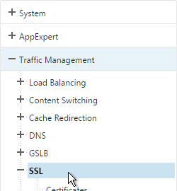
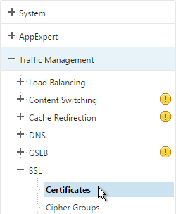
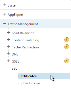
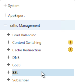
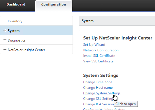
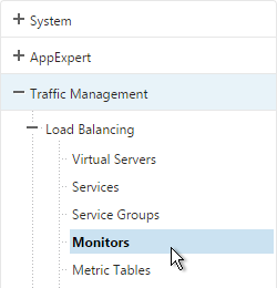
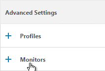
- On the left, expand Traffic Management, expand Load Balancing, and click Monitors.
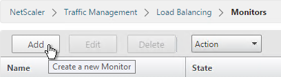
- On the right, click Add.
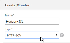
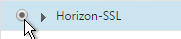
- Name it Horizon-SSL or similar.
- Change the Type drop-down to HTTP-ECV.
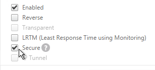
- On the Standard Parameters tab, in the Destination Port field, enter 443.

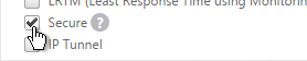
- Scroll down and check the box next to Secure.
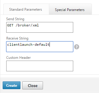
- On the Special Parameters tab, in the Send String section, enter
GET /broker/xml - In the Receive String section, enter
clientlaunch-default - Scroll down and click Create.
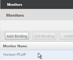
PCoIP Monitor
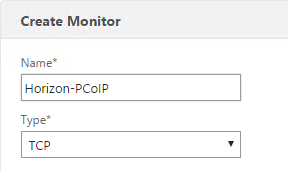
- On the right, click Add.
- Name it Horizon-PCoIP or similar.
- Change the Type drop-down to TCP.
- On the Standard Parameters tab, in the Destination Port field, enter 4172.
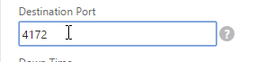
- Scroll down and click Create.

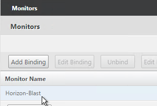
Blast Monitor
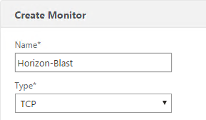
- On the right, click Add.
- Name it Horizon-Blast or similar.
- Change the Type drop-down to TCP.
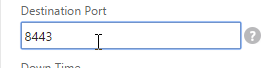
- On the Standard Parameters tab, in the Destination Port field, enter 8443.
- Scroll down and click Create.
Paired Connection Server Monitor
Note: the steps in this section do not apply to Access Points or internal Connection Servers.
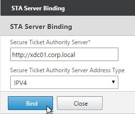
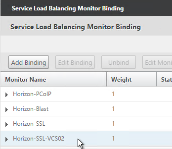
View Security Servers are paired with View Connection Servers. If the paired View Connection Server is down, then we should probably stop sending users to the corresponding View Security Server. Let’s create a monitor that has a specific IP address in it.
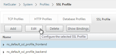
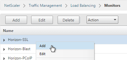
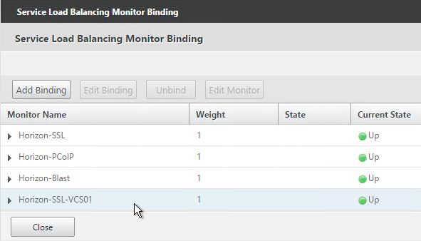
- Right-click the existing Horizon-SSL monitor and click Add.
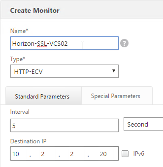
- Normally a monitor does not have any Destination IP defined, which means it uses the IP address of the service that it is bound to. However, we intend to bind this monitor to the View Security Server but we need it to monitor the paired View Connection Server, which is a different IP address. Type in the IP address of the paired View Connection Server. Then rename the monitor so it includes the View Connection Server name. Click Create.
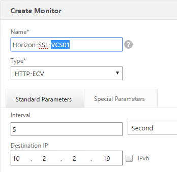
- Since we are embedding an IP address into the monitor, you have to create a separate monitor for each paired Connection Server IP. Create another monitor. Specify the IP of the other paired Connection Server. Click Create.
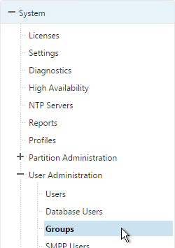
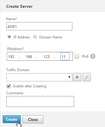
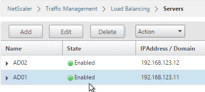
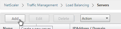
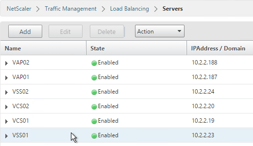
Load Balancing Servers
Create Server Objects for the DMZ Security Servers, DMZ Access Point appliances and the internal non-paired Connection Servers. Do not create Server Objects for the Paired Connection Servers.
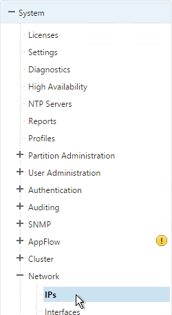
- On the left, expand Traffic Management, expand Load Balancing, and click Servers.
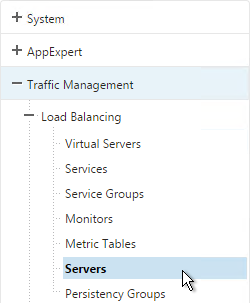
- On the right, click Add.
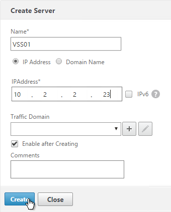
- Enter a descriptive server name, usually it matches the actual server name.
- Enter the IP address of the Access Point, Horizon Connection Server, or Horizon Security Server.
- Enter comments to describe the server. Click Create.
- Continue adding Access Points, Horizon Connection Servers, and/or Horizon Security Servers.
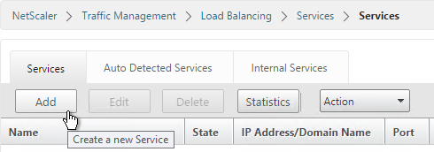
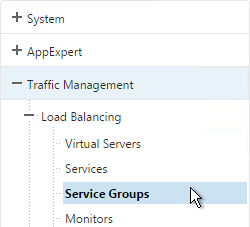
Load Balancing Services
Overview
Services vs Service Groups:
- For Security Servers, if the paired Connection Server is down, then we need the Security Server to go down too. One of the monitors bound to the Security Server contains the IP address of the paired Connection Server. Since each Security Server is paired with a different Connection Server, that means each Security Server will have a unique monitoring configuration. This precludes us from adding multiple Security Servers to a single Service Group since you can only have one monitor configuration for the entire Service Group. Instead, create separate Services (multiple port numbers) for each Security Server.
- Individual services per server are only needed for TCP 443. The other ports can be service groups.
- For Access Points, there is no special monitoring configuration and thus these appliances could be added to Service Groups (one for each port number).
- For internal Connection Servers (non-paired), there is no special monitoring configuration and thus these appliances could be added to one Service Group. Internal Connection Servers usually only need TCP 443 load balanced.
For Internal Connection Servers (not the paired servers), load balancing monitoring is very simple:
- Create a service group for SSL 443.
- To verify server availability, monitor port TCP 443 on the same server.
- If tunneling is disabled then internal users connect directly to View Agents and UDP/TCP 4172 and TCP 8443 are not used on Internal Connection Servers. There’s no need to create service groups and monitors for these ports.
Security Servers and Access Point appliances are more complex:
- For Blast Extreme protocol through Access Points, if UDP is not enabled, then you only need services for TCP 443. If UDP is enabled, then you also need load balancing services for UDP 443.
- For Blast Extreme protocol through View Security Servers, if UDP is not enabled, then you only need services for TCP 443 and TCP 8443. If UDP is enabled, then you also need load balancing services for UDP 8443.
- For PCoIP protocol, all traffic initially connects on TCP 443. The Horizon clients then connect to UDP 4172 on the same Security Server or Access Point. If 4172 is down, then 443 should be taken down. Bind monitors for each port to the TCP 443 service. If any of the monitors fails (e.g. 4172 is down), then TCP 443 is taken down and NetScaler will no longer forward traffic to TCP 443 on that particular server/appliance.
- Each Security Server is paired with an internal Connection Server. If the internal Connection Server is down then the Security Server should be taken down. This requires custom monitors for each Security Server. This is not a problem for Access Points.
Load Balancing Services Configuration Summary
The summaries are split into PCoIP vs Blast Extreme, and View Security Servers vs Access Points. If you are using both PCoIP and Blast Extreme, combine their configurations.
Two Access Points for Blast Extreme: if they are named VAP01 and VAP02, the load balancing service configuration for Blast Extreme in Horizon 7 (no PCoIP) is summarized as follows (scroll down for detailed configuration):
- Service Group, Protocol = SSL_BRIDGE
- Members = VAP01 and VAP02
- Port = 443
- Monitor = SSL (443)
- Service Group, Protocol = UDP (this service group is only needed if Blast Extreme UDP is enabled)
- Members = VAP01 and VAP02
- Port = 443
- Monitor = SSL (443) or ping
Two Access Points for PCoIP protocol: if they are named VAP01 and VAP02, the load balancing service configuration for PCoIP is summarized as follows (scroll down for detailed configuration):
- Service Group, Protocol = SSL_BRIDGE
- Members = VAP01 and VAP02
- Port = 443
- Monitor = SSL (443)
- Service Group, Protocol = TCP
- Members = VAP01 and VAP02
- Port = 4172
- Monitor = PCoIP (TCP 4172)
- Service Group, Protocol = UDP
- Members = VAP01 and VAP02
- Port = 4172
- Monitor = PCoIP (TCP 4172)
- Service Group, Protocol = SSL_BRIDGE
- Members = VAP01 and VAP02
- Port = 8443
- Monitor = Blast (8443)
- Service Group, Portocol = UDP
- Members = VAP01 and VAP02
- Port = 8443
- Monitor = Blast (8443)
Two Security Servers for Blast Extreme: if they are named VSS01 and VSS02, the load balancing service configuration for Blast Extreme in Horizon 7 (no PCoIP) is summarized as follows (scroll down for detailed configuration):
- Service Group, Protocol = SSL_BRIDGE
- Members = VSS01 and VSS02
- Port = 443
- Monitor = SSL (443)
- Service Group, Protocol = SSL_BRIDGE
- Members = VSS01 and VSS02
- Port = 8443
- Monitor = Blast (8443)
- Service Group, Protocol = UDP (this service group is only needed if Blast Extreme UDP is enabled)
- Members = VSS01 and VSS02
- Port = 8443
- Monitor = SSL (443) or ping
Two View Security Servers with PCoIP: If the View Security Servers are named VSS01 and VSS02, the load balancing service configuration for PCoIP is summarized as follows (scroll down for detailed configuration):
- Server = VSS01, Protocol = SSL_BRIDGE, Port = 443
- Monitors = PCoIP (TCP 4172), SSL (443), and Blast (8443)
- Monitor = SSL (443) for paired View Connection Server VCS01.
- Server = VSS02, Protocol = SSL_BRIDGE, Port = 443
- Monitors = PCoIP (TCP 4172), SSL (443), and Blast (8443)
- Monitor = SSL (443) for paired View Connection Server VCS02.
- Service Group, Protocol = UDP
- Members = VSS01 and VSS02
- Port = 443
- Monitor = SSL (443) or ping
- Service Group, Protocol = TCP
- Members = VSS01 and VSS02
- Port = 4172
- Monitor = PCoIP (TCP 4172)
- Service Group, Protocol = UDP
- Members = VSS01 and VSS02
- Port = 4172
- Monitor = PCoIP (TCP 4172)
- Service Group, Protocol = SSL_BRIDGE
- Members = VSS01 and VSS02
- Port = 8443
- Monitor = Blast (8443)
- Service Group, Portocol = UDP
- Members = VSS01 and VSS02
- Port = 8443
- Monitor = Blast (8443)
TCP 443 Load Balancing Services
Here are general instructions for the TCP 443 Horizon load balancing services. These instructions detail the more complicated Security Server configuration, since each Security Server needs to monitor its paired Connection Servers. If you are load balancing Access Point or internal Connection Servers, you could configure a Service Group instead of individual services. See the above configuration summaries for your specific configuration.
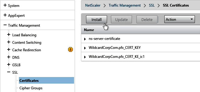
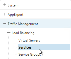
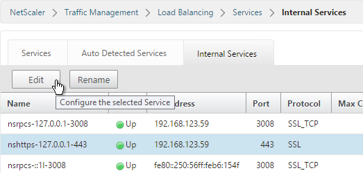
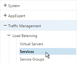
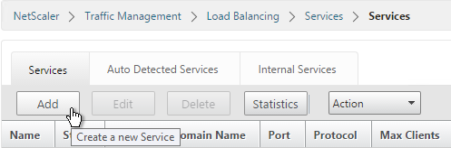
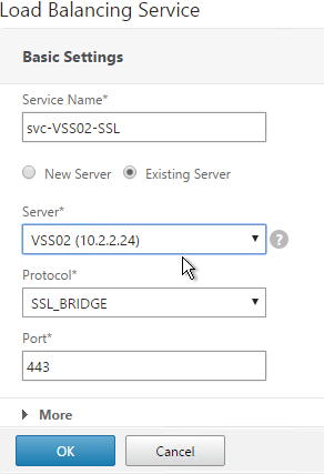
- On the left, expand Traffic Management, expand Load Balancing, and click Services.
- On the right, click Add.
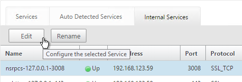
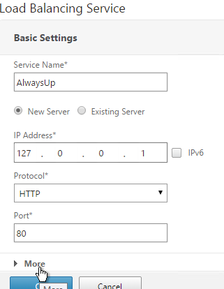
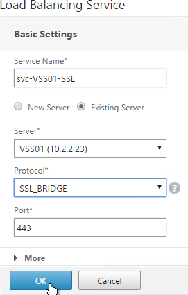
- Give the Service a descriptive name (e.g. svc-VSS01-SSL).
- Change the selection to Existing Server and select the Access Point, Security Server or internal (non-paired) Connection Server you created earlier.
- Change the Protocol to SSL_BRIDGE, and click OK.
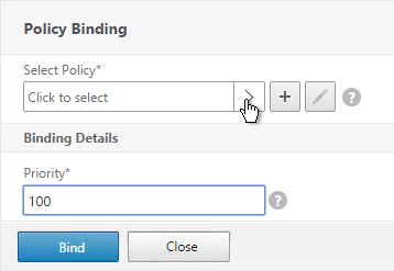
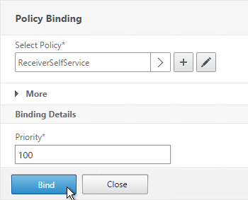
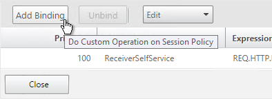
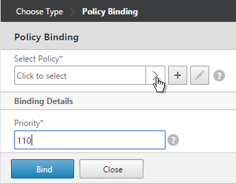
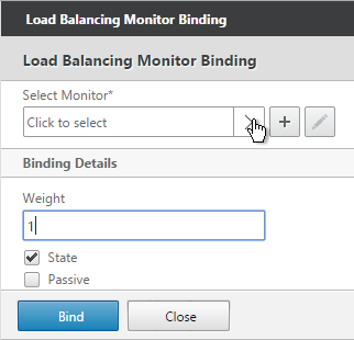
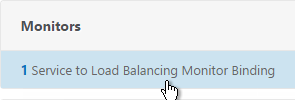
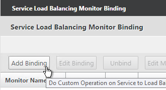
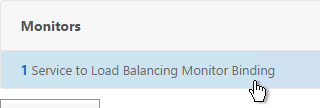
- On the left, in the Monitors section, click where it says 1 Service to Load Balancing Monitor Binding.
- Ignore the current monitor and click Add Binding.
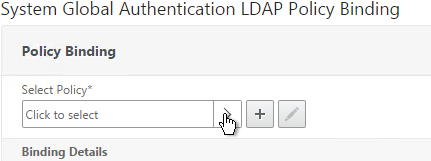
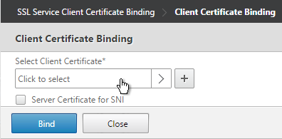
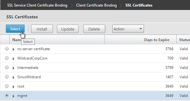
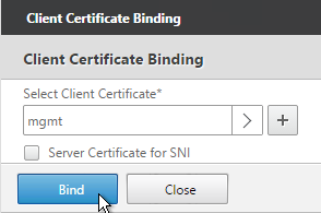
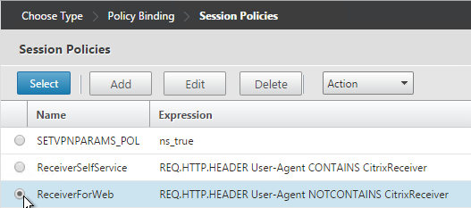
- Click the arrow next to Click to select.
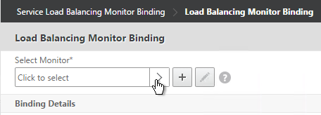
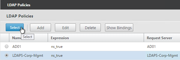
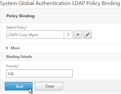
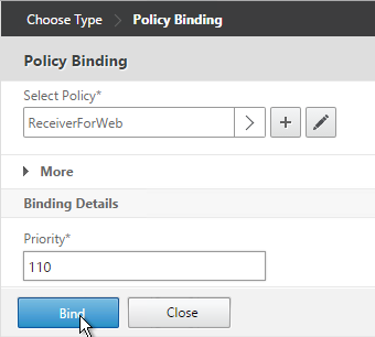
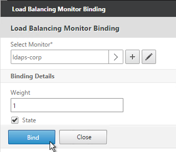
- Select the Horizon-SSL monitor and click Select.

- Then click Bind.

- If you are load balancing PCoIP through a View Security Server or Access Point, add monitors for PCoIP Secure Gateway (4172) and Blast Secure Gateway (8443) too. If 4172 or 8443 fails, then 443 needs to be marked DOWN.
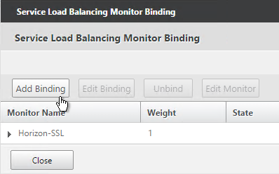
- If this is a Security Server, also add a monitor that has the IP address of the paired Connection Server. If the paired Connection Server is down, then the Security Server needs to marked as DOWN so NetScaler needs to stop sending connections to this Security Server.
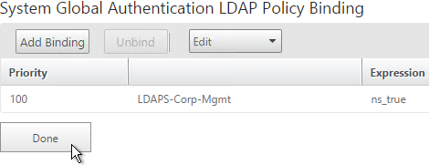
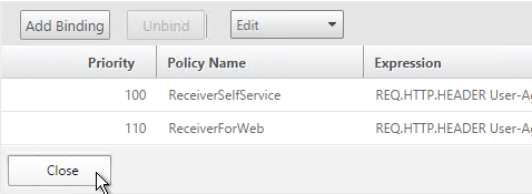
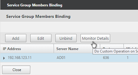
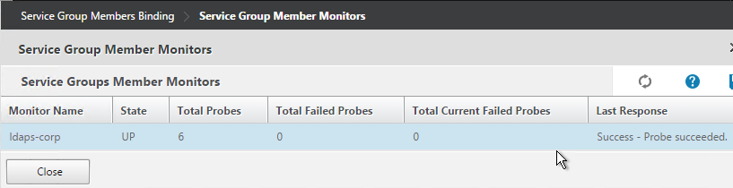
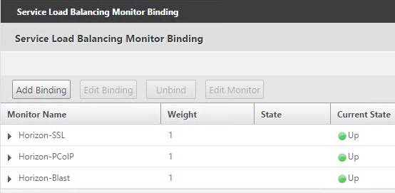
- The Last Response should indicate Success. If you bound multiple monitors to the Service, then the member will only be UP if all monitors succeed. There’s a refresh button on the top-right. Click Close when done.
- Then click Done.

- Right-click the first service and click Add.
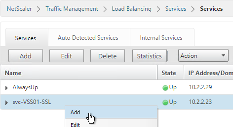
- Change the name to match the second Horizon Server or Access Point.
- Select Existing Server and use the Server drop-down to select to the second Horizon Server.
- The remaining configuration is identical to the first server. Click OK.
- You will need to configure the monitors again. They will be identical to the first server except for the monitoring of the paired View Connection Server. Click Done when done.
Other Ports Load Balancing Services
Here are general instructions for the remaining Horizon services. These instructions use Service Groups but you could just as easily add Services instead. See the above summaries for your specific configuration.
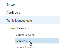
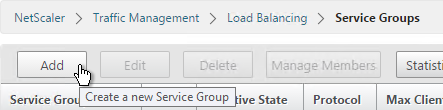
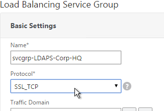
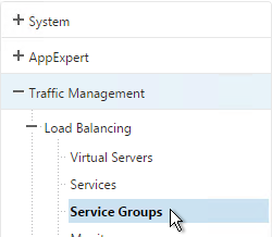
- On the left, go to Traffic Mgmt > Load Balancing > Service Groups.
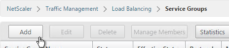
- On the right, click Add.
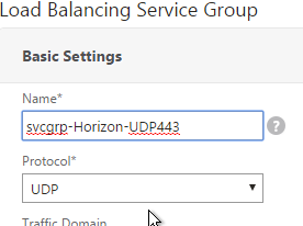
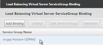
- Name it svcgrp-Horizon-UDP443 or similar. UDP 443 is for Blast Extreme in Horizon 7 through Access Points. If View Security Servers, the name should be svcgrp-Horizon-UDP8443.
- Change the Protocol to UDP. Click OK.
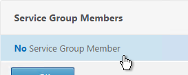
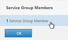
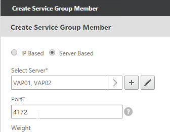
- Click where it says No Service Group Member.
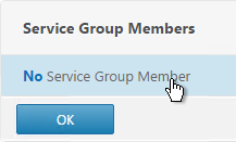
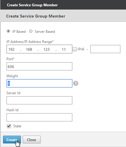
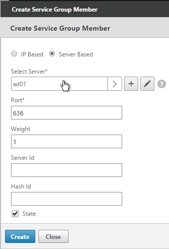
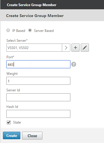
- Change the selection to Server Based and then click Click to select.
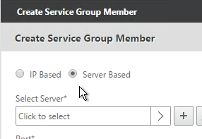
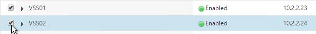
- Select your multiple Security Servers or multiple Access Points and click Select.
- If Access Points, enter 443 as the Port. If View Security Servers, enter 8443 as the port. Click Create.
- Click OK.
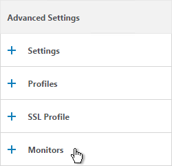
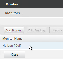
- On the right, in the Advanced Settings column, add the Monitors section.
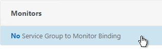
- Click where it says No Service Group to Monitor Binding.
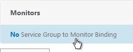
- Click to select.
- Select the Horizon-SSL monitor, click Select, and then click Bind.
- Click Done.
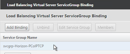
- Add another Service Group for PCoIP on TCP 4172.
- Name = svcgrp-Horizon-PCoIPTCP or similar.
- Protocol = TCP
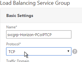
- Members = multiple Security Servers or multiple Access Points.
- Port = 4172.
- Monitors = Horizon-PCoIP. You can add the other monitors if desired.
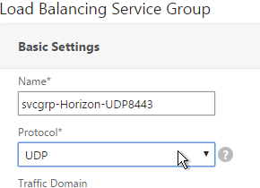
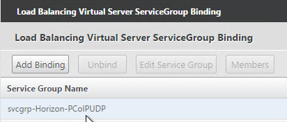
- Add another Service Group for PCoIP on UDP 4172.
- Name = svcgrp-Horizon-PCoIPUDP or similar.
- Protocol = UDP
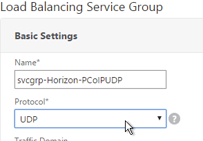
- Members = multiple Security Servers or multiple Access Points
- Port = 4172.
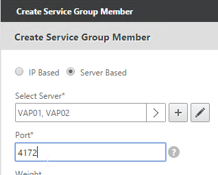
- Monitors = Horizon-PCoIP. You can add the other monitors if desired.
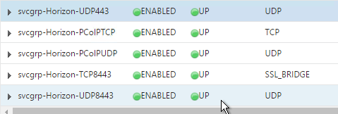
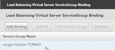
- Add another Service Group for SSL_BRIDGE 8443.
- Name = svcgrp-Horizon-TCP8443 or similar.
- Protocol = SSL_BRIDGE
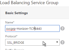
- Members = multiple Security Servers or multiple Access Points
- Port = 8443.
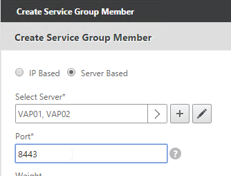
- Monitors = Horizon-Blast. You can add the other monitors if desired.
- If you haven’t done this already, add another Service Group for UDP 8443 (Blast Extreme in Horizon 7).
- Name = svcgrp-Horizon-UDP8443 or similar.
- Protocol = UDP
- Members = multiple Security Servers or multiple Access Points
- Port = 8443.
- Monitors = Horizon-Blast. You can add the other monitors if desired.
- The five service groups should look something like this:
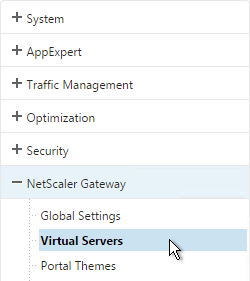
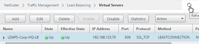
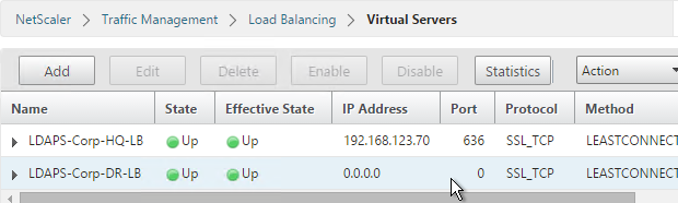
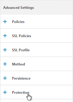
Load Balancing Virtual Servers
Create separate load balancing vServers for internal and DMZ.
- Internal VIP load balances the non-paired Internal Connections Servers. Access Point appliances also use this VIP to access the internal Connection Servers.
- DMZ VIP load balances the Security Servers or Access Point appliances.
The paired View Connection Servers do not need to be load balanced.
For the internal Connection Servers you only need a load balancer for SSL_BRIDGE 443. If tunneling is disabled then you don’t need load balancers for the other ports (UDP/TCP 4172 and SSL_BRIDGE 8443).
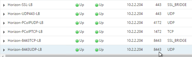
However, Security Servers and Access Points listen on more ports so you will need separate load balancers for each port number. Here is a summary of their Virtual Servers, all listening on the same IP address. Depending on the configured protocol, you might not need all of these Virtual Servers.
- Virtual Server on SSL_BRIDGE 443 – bind both Horizon SSL_BRIDGE 443 Services.
- Virtual Server on UDP 443 (Horizon 7) – bind the UDP 443 service group.
- Virtual Server on UDP 4172 – bind the PCoIPUDP service group.
- Virtual Server on TCP 4172 – bind the PCoIPTCP service group.
- Virtual Server on SSL_BRIDGE 8443 – bind the SSL_BRIDGE 8443 service group.
- Virtual Server on UDP 8443 (Horizon 7) – bind the UDP 8443 service group.
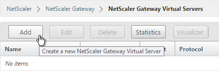
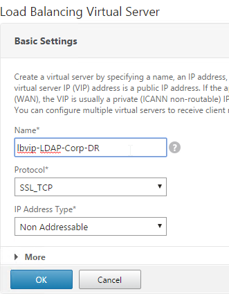
Do the following to create the Virtual Servers:
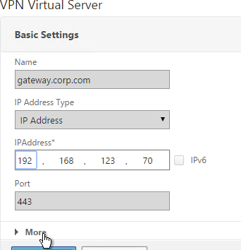
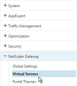
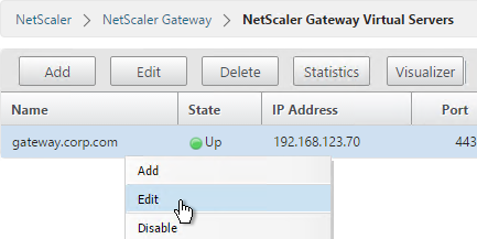
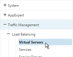
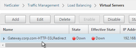
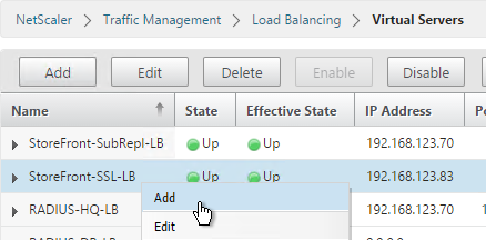
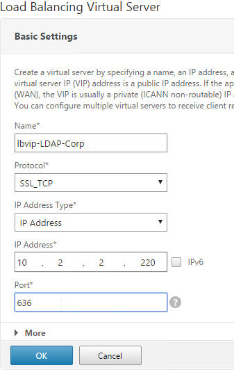
- On the left, under Traffic Management > Load Balancing, click Virtual Servers.
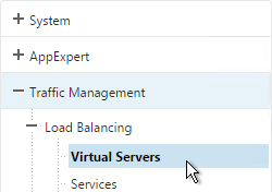
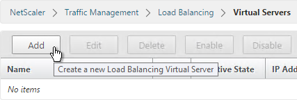
- On the right click Add.
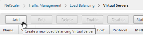
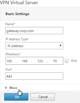
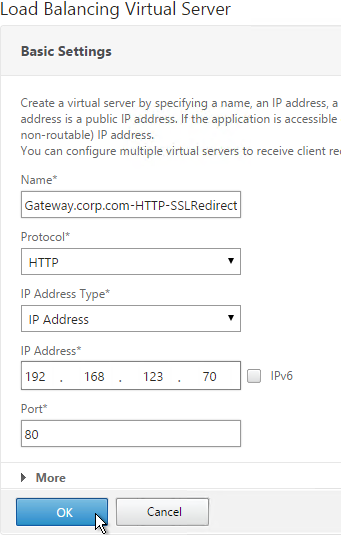
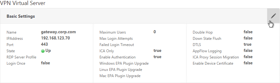
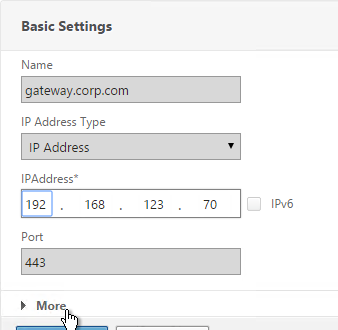
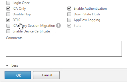
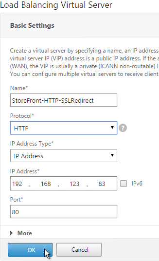
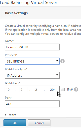
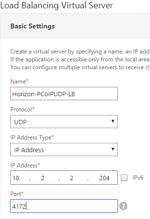
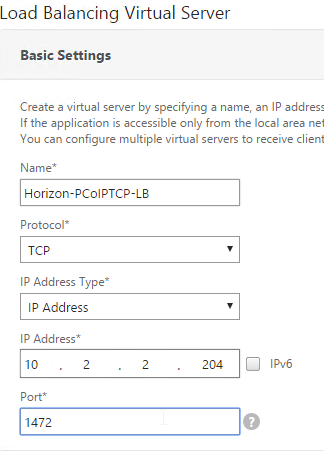
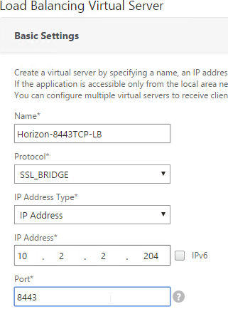
- Name it Horizon-SSL-LB or similar.
- Change the Protocol to SSL_BRIDGE.
- Specify a new VIP. This one VIP will be used for all of the Virtual Servers.
- Enter 443 as the Port.
- Click OK.
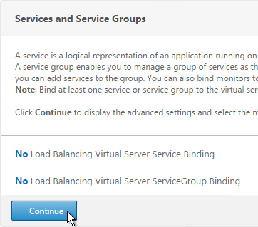
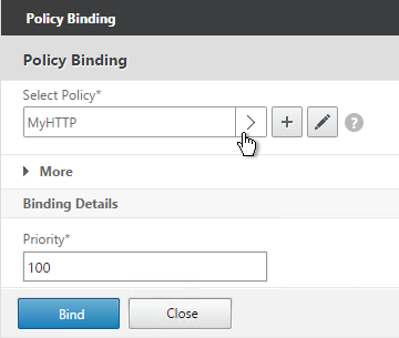
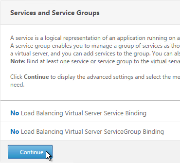
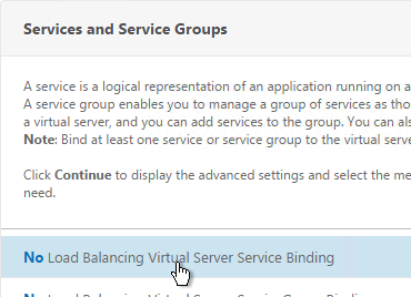
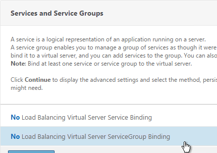
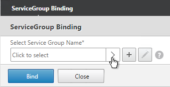
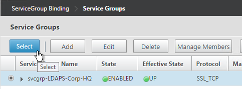
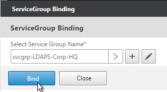
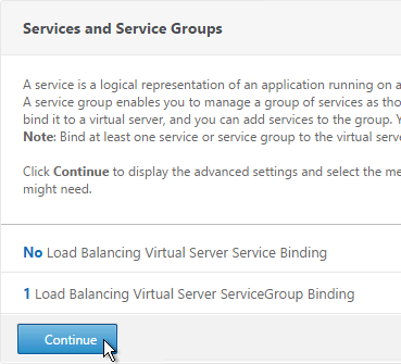
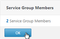
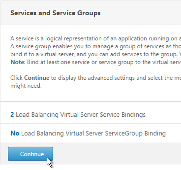
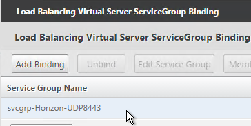
- On the left, in the Services and Service Groups section, click where it says No Load Balancing Virtual Server Service Binding.
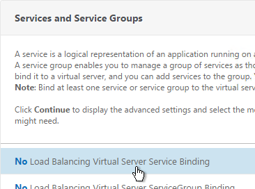
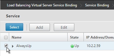
- Click the arrow next to Click to select.
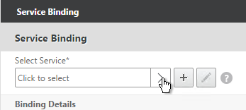
- Select the two View-SSL Services and click Select.
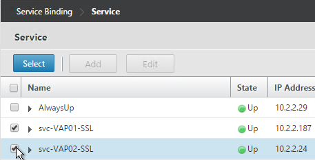
- Click Bind.
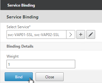
- Click Continue.
- Then click Done. Persistency will be configured later.

- If this is Horizon 7, and if this is an Access Point, then create another Load Balancing Virtual Server for UDP 443:
- Same VIP as the TCP 443 Load Balancer.
- Protocol = UDP, Port = 443
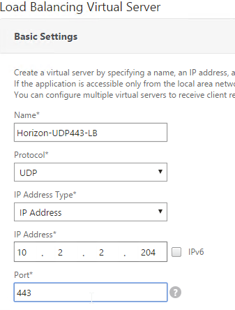
- Service Group Binding = the UDP 443 Service Group
- If this is a Security Server or Access Point, then create another Load Balancing Virtual Server for PCoIP UDP 4172:
- Same VIP as the 443 Load Balancer.
- Protocol = UDP, Port = 4172
- Service Group Binding = the PCoIP UDP Service Group.
- If this is a Security Server or Access Point, then create another Load Balancing Virtual Server for PCoIP TCP 4172:
- Same VIP as the 443 Load Balancer.
- Protocol = TCP, Port = 4172
- Service Group Binding = the PCoIP TCP Service Group
- If this is a Security Server or Access Point, then create another Load Balancing Virtual Server for SSL_BRIDGE 8443:
- Same VIP as the 443 Load Balancer.
- Protocol = SSL_BRIDGE, Port = 8443
- Service Group Binding = the TCP 8443 SSL_BRIDGE Service Group
- If this is a Security Server or Access Point, then create another Load Balancing Virtual Server for UDP 8443:
- Same VIP as the 443 Load Balancer.
- Protocol = UDP, Port = 8443
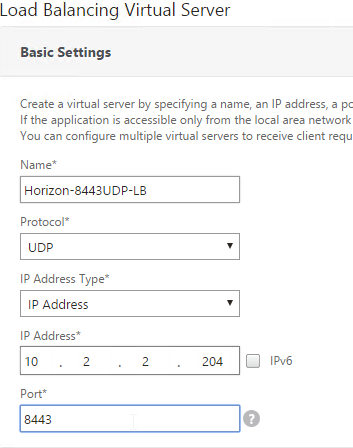
- Service Group Binding = the UDP 8443 SSL_BRIDGE Service Group
- This gives you six Virtual Servers on the same VIP but different protocols and port numbers.
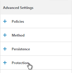
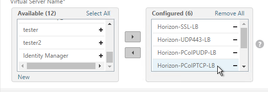
Persistency Group
For Security Servers and Access Points, users will first connect to SSL_BRIDGE 443 and be load balanced. Subsequent connections to the other port numbers must go to the same load balanced server. Create a Persistency Group to facilitate this.
For internal View Connection Servers, then you probably only have one SSL_BRIDGE load balancer for those servers, and thus you could configure persistence directly on that one load balancing vServer instead of creating a Persistency Group. However, since the Security Servers and Access Points have multiple load balancing vServers on different ports, then you need to bind them together into a Persistency Group.
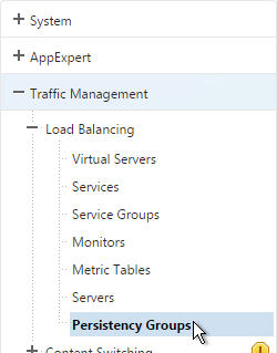
- On the left, under Traffic Management, expand Load Balancing and click Persistency Groups.
- On the right, click Add.
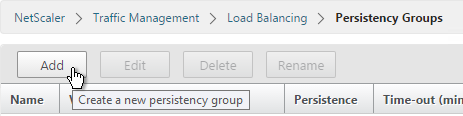
- Give the Persistency Group a name (e.g. Horizon).
- Change the Persistence to SOURCEIP.
- Enter a timeout that is equal to or greater than the timeout in Horizon View Administrator, which defaults to 10 hours (600 minutes).
- In the Virtual Server Name section, click Add.
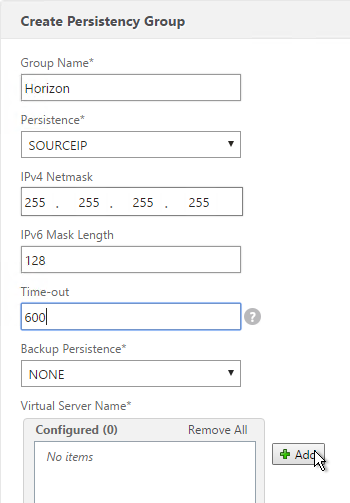
- Move all six Security Server / Access Point Load Balancing Virtual Servers to the right. Click Create.
CLI Commands
Here’s a list of CLI commands for the most basic configuration of two Access Points with Blast Extreme only (no PCoIP):
add server VAP01 10.2.2.187
add server VAP02 10.2.2.24
add lb monitor Horizon-SSL HTTP-ECV -send "GET /broker/xml" -recv clientlaunch-default -secure YES
add serviceGroup svcgrp-Horizon-SSL SSL_BRIDGE
add serviceGroup svcgrp-Horizon-UDP443 UDP
bind serviceGroup svcgrp-Horizon-SSL VAP01 443
bind serviceGroup svcgrp-Horizon-SSL VAP02 443
bind serviceGroup svcgrp-Horizon-SSL -monitorName Horizon-SSL
bind serviceGroup svcgrp-Horizon-UDP443 VAP01 443
bind serviceGroup svcgrp-Horizon-UDP443 VAP02 443
bind serviceGroup svcgrp-Horizon-UDP443 -monitorName Horizon-SSL
add lb vserver Horizon-SSL-LB SSL_BRIDGE 10.2.2.204 443
add lb vserver Horizon-UDP443-LB UDP 10.2.2.204 443
bind lb vserver Horizon-SSL-LB svcgrp-Horizon-SSL
bind lb vserver Horizon-UDP443-LB svcgrp-Horizon-UDP443
bind lb group Horizon Horizon-SSL-LB
bind lb group Horizon Horizon-UDP443-LB
set lb group Horizon -persistenceType SOURCEIP -timeout 600
Here’s a list of CLI commands for the more complicated Security Server configuration:
add server VSS01 10.2.2.187
add server VSS02 10.2.2.24
add lb monitor Horizon-PCoIP TCP -destPort 4172
add lb monitor Horizon-Blast TCP -destPort 8443
add lb monitor Horizon-SSL HTTP-ECV -send "GET /broker/xml" -recv clientlaunch-default -secure YES
add lb monitor Horizon-SSL-VCS01 HTTP-ECV -send "GET /broker/xml" -recv clientlaunch-default -destIP 10.2.2.19 -destPort 443 -secure YES
add lb monitor Horizon-SSL-VCS02 HTTP-ECV -send "GET /broker/xml" -recv clientlaunch-default -destIP 10.2.2.20 -destPort 443 -secure YES
add service svc-VSS01-SSL VSS01 SSL_BRIDGE 443
add service svc-VSS02-SSL VSS02 SSL_BRIDGE 443
bind service svc-VSS02-SSL -monitorName Horizon-SSL-VCS02
bind service svc-VSS02-SSL -monitorName Horizon-SSL
bind service svc-VSS02-SSL -monitorName Horizon-Blast
bind service svc-VSS02-SSL -monitorName Horizon-PCoIP
bind service svc-VSS01-SSL -monitorName Horizon-SSL-VCS01
bind service svc-VSS01-SSL -monitorName Horizon-Blast
bind service svc-VSS01-SSL -monitorName Horizon-PCoIP
bind service svc-VSS01-SSL -monitorName Horizon-SSL
add serviceGroup svcgrp-Horizon-UDP443 UDP
add serviceGroup svcgrp-Horizon-PCoIPTCP TCP
add serviceGroup svcgrp-Horizon-PCoIPUDP UDP
add serviceGroup svcgrp-Horizon-TCP8443 SSL_BRIDGE
add serviceGroup svcgrp-Horizon-UDP8443 UDP
bind serviceGroup svcgrp-Horizon-UDP443 VSS01 443
bind serviceGroup svcgrp-Horizon-UDP443 VSS02 443
bind serviceGroup svcgrp-Horizon-UDP443 -monitorName Horizon-SSL
bind serviceGroup svcgrp-Horizon-PCoIPTCP VSS01 4172
bind serviceGroup svcgrp-Horizon-PCoIPTCP VSS02 4172
bind serviceGroup svcgrp-Horizon-PCoIPTCP -monitorName Horizon-PCoIP
bind serviceGroup svcgrp-Horizon-PCoIPUDP VSS01 4172
bind serviceGroup svcgrp-Horizon-PCoIPUDP VSS02 4172
bind serviceGroup svcgrp-Horizon-PCoIPUDP -monitorName Horizon-PCoIP
bind serviceGroup svcgrp-Horizon-TCP8443 VSS01 8443
bind serviceGroup svcgrp-Horizon-TCP8443 VSS02 8443
bind serviceGroup svcgrp-Horizon-TCP8443 -monitorName Horizon-Blast
bind serviceGroup svcgrp-Horizon-UDP8443 VSS01 8443
bind serviceGroup svcgrp-Horizon-UDP8443 VSS02 8443
bind serviceGroup svcgrp-Horizon-UDP8443 -monitorName Horizon-Blast
add lb vserver Horizon-SSL-LB SSL_BRIDGE 10.2.2.204 443
add lb vserver Horizon-UDP443-LB UDP 10.2.2.204 443
add lb vserver Horizon-PCoIPUDP-LB UDP 10.2.2.204 4172
add lb vserver Horizon-PCoIPTCP-LB TCP 10.2.2.204 4172
add lb vserver Horizon-8443TCP-LB SSL_BRIDGE 10.2.2.204 8443
add lb vserver Horizon-8443UDP-LB UDP 10.2.2.204 8443
bind lb vserver Horizon-SSL-LB svc-VSS01-SSL
bind lb vserver Horizon-SSL-LB svc-VSS02-SSL
bind lb vserver Horizon-UDP443-LB svcgrp-Horizon-UDP443
bind lb vserver Horizon-PCoIPTCP-LB svcgrp-Horizon-PCoIPTCP
bind lb vserver Horizon-PCoIPUDP-LB svcgrp-Horizon-PCoIPUDP
bind lb vserver Horizon-8443TCP-LB svcgrp-Horizon-TCP8443
bind lb vserver Horizon-8443UDP-LB svcgrp-Horizon-UDP8443
bind lb group Horizon Horizon-SSL-LB
bind lb group Horizon Horizon-UDP443-LB
bind lb group Horizon Horizon-PCoIPUDP-LB
bind lb group Horizon Horizon-PCoIPTCP-LB
bind lb group Horizon Horizon-8443TCP-LB
bind lb group Horizon Horizon-8443UDP-LB
set lb group Horizon -persistenceType SOURCEIP -timeout 600
Horizon View Configuration – Security Servers
This section is not needed for Access Points. For Access Points, the secure gateways should be disabled, not enabled.
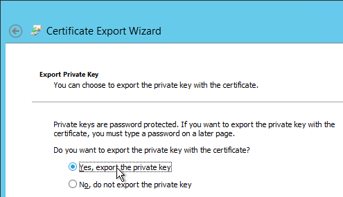
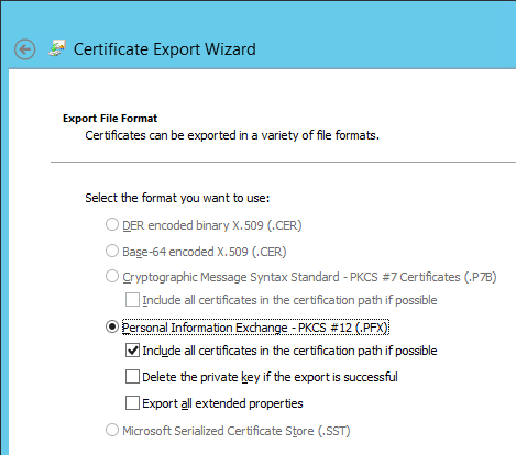
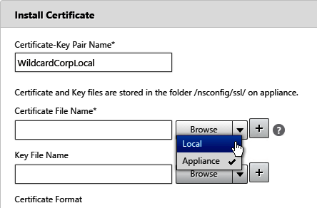
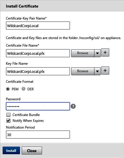
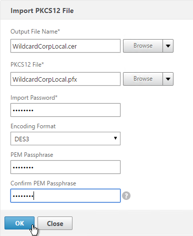
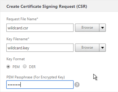
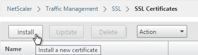
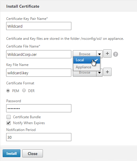
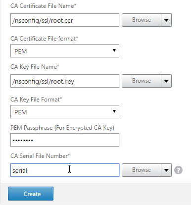
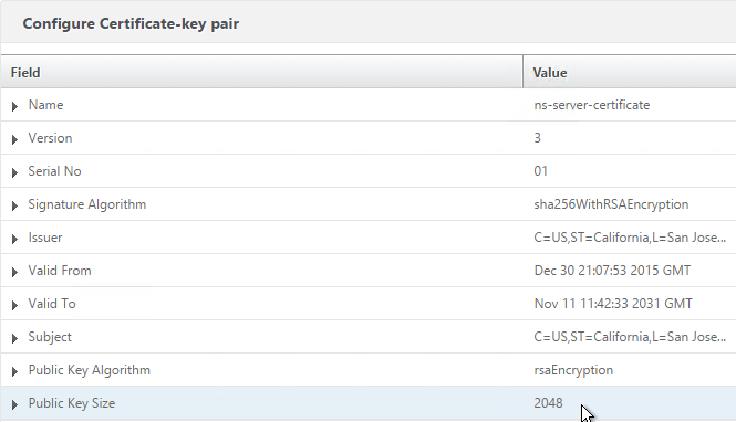
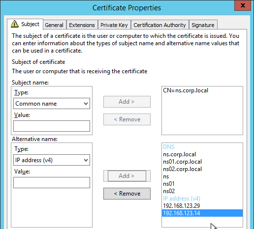
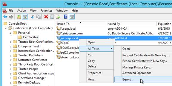
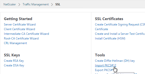
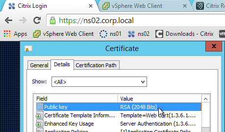
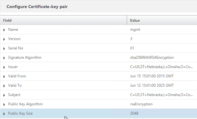
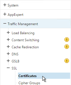
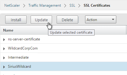
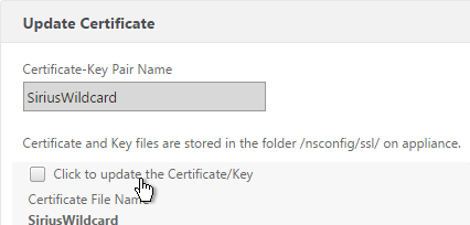
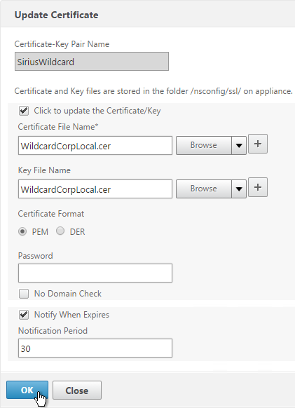
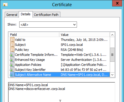
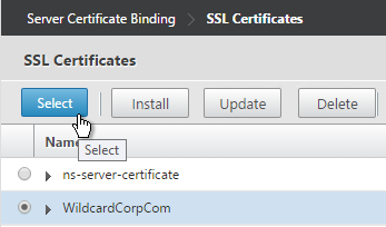
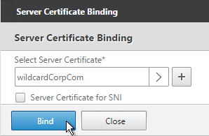
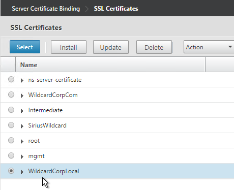
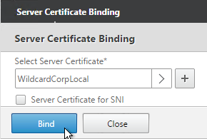
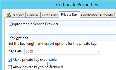
- On the Security Servers (or Connection Servers), request a certificate that matches the FQDN that resolves to the Load Balancing VIP.
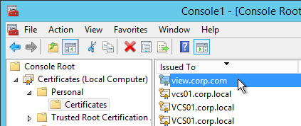
- Make sure the private key is exportable.
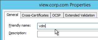
- Set the Friendly Name to vdm and restart the View Security Server services.
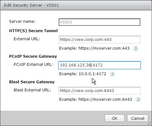
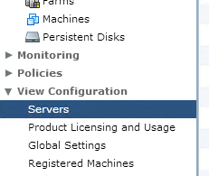
- In View Administrator, go to View Configuration > Servers.
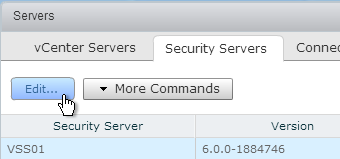
- On the right, switch to the Security Servers tab.
- Highlight a server and click Edit.
- Change the URLs to the FQDN that resolves to the load balancing VIP.
- Change the PCoIP URL to the VIP. For View Security Servers, this is typically a public IP that is NAT’d to the DMZ Load Balancing VIP.